Oe520-xx-m round p.d, Zone damper assembly w/ modular connectors, Zone damper sizing – Orion System OE742-XX-VAVZ User Manual
Page 9: Zone damper selection data
Form: Orion-OE520XX-M-RndDmpr-Sub-01G
Page
2 of 2
Zone Damper Sizing
Use a load program to determine the peak
load for each zone. These calculations will be
used to select VAV/Zone Damper sizes.
The Orion Systems utilize a typical low
pressure duct design. To reduce noise
problems, duct pressures should not exceed
1” W.C.
Primary trunk ducts used with Orion systems
should not be “undersized”. This is especially
true of “pressure dependent” systems. With
larger trunk ducts, it is easier to assure
relatively constant pressure to each Zone
Damper. Runs should be as short as
possible, and the trunk duct system kept as
symmetrical as possible to facilitate system
balancing. Wherever possible, run the trunk
ducts above corridors and locate the Zone
Dampers above corridors to reduce the noise
in the space and facilitate service of the
valves. Trunk ducts should be sized for no
more than 0.1” W.C. drop per 100 ft. of duct,
and a maximum duct velocity of 2000 FPM.
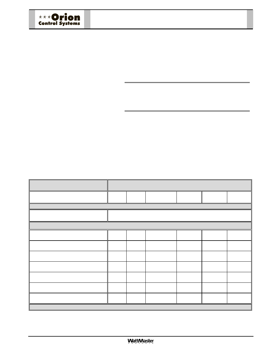
Zone Damper Selection Data
OE520-XX-M Round Pressure Dependent
Zone Damper Assembly W/ Modular Connectors
Zone Damper Round Duct Size
(Area Ft
2
)
6”
(0.196)
8”
(0.349)
10”
(0.545)
12”
(0.785)
14”
(1.069)
16”
(1.396)
Velocity Through VAV/Zone Damper
FPM
Airflow Through VAV/Zone Damper - CFM
(
P
S
inches W.C. w/ Damper Full Open)
500
98
(< 0.01)
175
(< 0.01)
273
(< 0.01)
393
(< 0.01)
535
(< 0.01)
698
(< 0.01)
750
147
(0.01)
262
(0.01)
409
(0.01)
589
(< 0.01)
802
(< 0.01)
1047
(< 0.01)
1000
196
(0.015)
349
(0.015)
545
(0.01)
785
(< 0.01)
1069
(< 0.01)
1396
(< 0.01)
1250
245
(0.025)
436
(0.02)
681
(0.015)
981
(0.015)
1336
(0.015)
1745
(0.015)
1500
294
(0.035)
523
(0.035)
818
(0.022)
1178
(0.020)
1604
0.020)
2094
(0.020)
1750
343
(0.045)
611
(0.035)
954
(0.034)
1374
(0.030)
1871
(0.030)
2443
(0.025)
2000
392
(0.065)
698
(0.043)
1090
(0.040)
1570
(0.040)
2138
(0.040)
2792
(0.030)
WattMaster reserves the right to change specifications without notice
Using the maximum acceptable velocity for a branch duct
(typically 1000-1500 FPM for minimal noise), find the smallest
Zone Damper that will deliver the required CFM as determined
by the load program. Locate the branch velocity used in the duct
design program in the left hand column of the Zone Damper
Selection Data table. Move across the table and find the Zone
Damper, which will provide the acceptable CFM to meet the zone
airflow requirements.
Note:
Compare the Zone Damper size selected against the
duct size to determine if the next size up or down will
provide acceptable performance without requiring a
transition fitting.
Up to a maximum of two Slaved Zone Dampers may be slaved
together with the main Zone Damper for large zones. This design
should be reserved only for situations when it is not practical to
use a single Zone Damper. See the AZ-300-RS Round Slaved
Zone Damper submittal sheet for information regarding
application and selection of Round Slaved Zone Dampers.
OE520-XX-M Round P.D.
Zone Damper
Assembly W/ Modular Connectors