Vav/zone worksheet – Orion System OE742-XX-VAVZ User Manual
Page 40
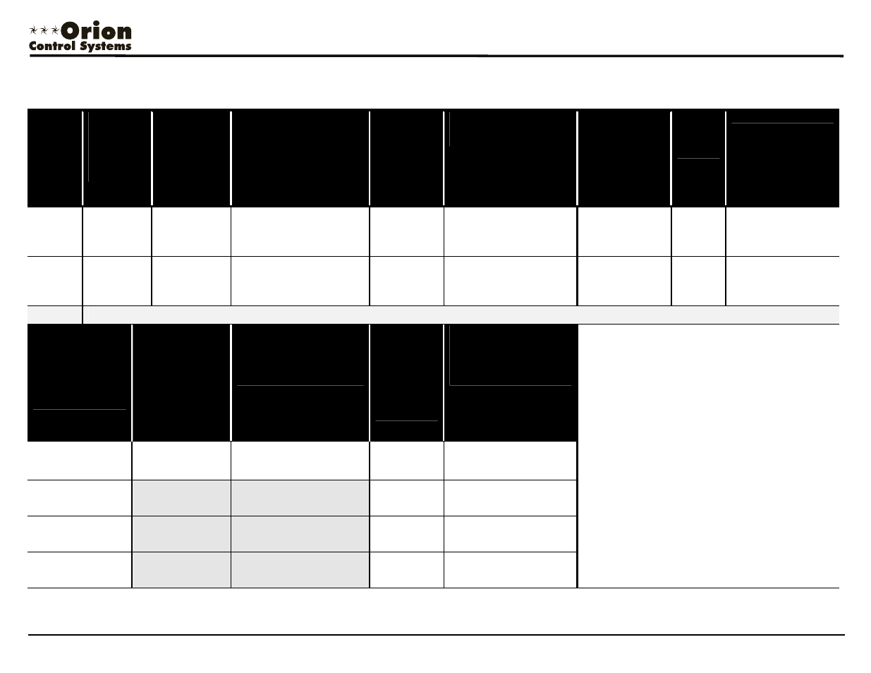
VAV/Zone Worksheet
Form: ORION-VAVZoneWorksheet1B.doc
Page
8 of 8
Project Name: _____________________________________________
Local Loop Number:
______
Total Qty. Of VAV/Zone Controllers on Loop:
_________
MiniLink PD Address For This Loop:
__________
Total Number Of Power/Comm Boards On Loop: _________
Note: See End Of VAV/Zone Controller Address List For
Power/Comm Board Cable Selection.
VAV/Zon
e
Address
VAV/Zone
Controller
Description,
Location Or
Tag
Number
Estimated
Power/Comm
Cable Length
From
Power/Comm
Board To
Controller
(If Required)
Selected Power/Comm
Cable Length From
Power/Comm Board To
Controller
(If Required)
Estimated
Power/Com
m Cable
Length To
Next
Controller
Selected Power/Com
Cable Length
To Next Controller
Selected
Room
Sensor Modular
or Digital Cable
Length
Type
Of
Terminal
Unit
Type Of Heat
57
3
Ft.
□ 25 Ft. □ 40 Ft. □
80 Ft. □ 120 Ft. □
Ext.-10 Ft. □ 20 Ft. □
3
Ft.
□ 25 Ft. □ 40 Ft. □
80 Ft. □ 120 Ft. □
Ext.-10 Ft. □ 20 Ft. □
5 Ft. □ 10 Ft. □
25 Ft. □ 40 Ft. □
80 Ft. □
120 Ft. □
160 Ft. □
NF □
SF □
PF □
EL-STGD □ EL-SCR □
HW-ON-OFF □
HW-MOD □
None □
58
3
Ft.
□ 25 Ft. □ 40 Ft. □
80 Ft. □ 120 Ft. □
Ext.-10 Ft. □ 20 Ft. □
3
Ft.
□ 25 Ft. □ 40 Ft. □
80 Ft. □ 120 Ft. □
Ext.-10 Ft. □ 20 Ft. □
5 Ft. □ 10 Ft. □
25 Ft. □ 40 Ft. □
80 Ft. □
120 Ft. □
160 Ft. □
NF □
SF □
PF □
EL-STGD □ EL-SCR □
HW-ON-OFF □
HW-MOD □
None □
59
This Address Is Reserved For The VCM-X Controller That Is Serving The VAV/Zone Controllers
Power/Comm
Boards
Qty Of Required
Power/Comm
Boards May Vary
Depending On
Installation
Estimated
Power/Comm
Cable Length
From
Power/Comm
Board To MiniLink
PD
Only Required For
First Power/Comm
Board On Loop
Selected Power/Comm
Cable Length From
Power/Comm Board To
MiniLink PD
Estimated
Power/Com
m Cable
Length To
Next
Power/Com
m Board
(If Required)
Selected Power/Com
Cable Length
To Next Power/Comm
Board
(If Required
NOTE:
Power/Comm Board maximum transformer size =
100VA. This is due to the board circuitry and fusing.
Each modular device is to be calculated at 6VA. This
allows for a maximum of 16 devices per
Power/Comm board. If more than 16 devices are
required, multiple Power/Comm boards must be
used.
No more than 6 modular devices allowed per branch
circuit. (The Power/Comm board has a total of 4
branch circuits)
The longest total run per branch circuit is 240 Ft.
This is due to voltage drop on the prefabricated
cable.
Power/Comm
Board #1
3
Ft.
□ 25 Ft. □ 40 Ft. □
80 Ft. □ 120 Ft. □
Ext.-10 Ft. □ 20 Ft. □
3 Ft. □ 25 Ft. □ 40 Ft. □
80 Ft. □ 120 Ft. □
Ext.-10 Ft. □ 20 Ft. □
Power/Comm
Board #2
3 Ft. □ 25 Ft. □ 40 Ft. □
80 Ft. □ 120 Ft. □
Ext.-10 Ft. □ 20 Ft. □
Power/Comm
Board #3
3 Ft. □ 25 Ft. □ 40 Ft. □
80 Ft. □ 120 Ft. □
Ext.-10 Ft. □ 20 Ft. □
Power/Comm
Board #4
3 Ft. □ 25 Ft. □ 40 Ft. □
80 Ft. □ 120 Ft. □
Ext.-10 Ft. □ 20 Ft. □
[NF = Non Fan Terminal] [SF = Series Flow Fan Terminal] [PF = Parallel Flow Fan Terminal]
[EL-STGD = Electric Heat - Staged] [EL-SCR = Electric Heat - SCR Controller] [HW-ON-OFF = Hot water Heat - On/Off Control] [HW-MOD = Hot Water - Modulating Control]