One condenser head pressure module, Appendix for version 1.06 and earlier, Technical guide – Orion System One Condenser Head Pressure Module User Manual
Page 21: Stand-alone wiring, Condenser fan ecm motor, Condenser signal
Technical Guide
One Condenser Head Pressure Module
21
Appendix for Version 1.06 and Earlier
SIG
GND
+V
BK
RD
WH
24 VAC Transformer
3 VA Minimum
Line Voltage
24 V
A
C
GND
WARNING!!
Observe Polarity! All boards
must be wired with GND-to-GND
and 24 VAC-to-24 VAC. Failure
to observe polarity could result in
damage to the boards.
OE370-23-HP1C
One Condenser Head Pressure Module
+5V
SIG 2
GND
OP
T
IO
N
S
ALARM
ANALOG
STAT
+5V
COMM
GND
SIG 4
GND
BIN 2
R1
R2
GND
RELAYS
ADDRESS
SIG 3
+5V
GND
BIN 1
COM
+5V
SIG 1
R3
R4
Rc
AO1
AO2
PWM1-
PWM1+
PWM2-
PWM2+
OPTIONS Dipswitch
is Used for Setting
the Head Pressure
Setpoint if Not Using
Default Setpoint.
SIG
GND
+V
BK
RD
WH
SIG
GND
+V
BK
RD
WH
SIG
GND
+V
BK
RD
WH
Head Pressure Transducers
0 - 667 PSI
(One Per Refrigerant Circuit)
PWR
Set ADDRESS Dip Switch 1 to
ON for Water Cooled or to
OFF for Air Cooled. Currently
showing OFF for Air Cooled.
Set ADDRESS Dip Switch 2 to
OFF for R410-A Refrigerant or
to ON for R22 Refrigerant.
Currently showing OFF for
R410-A Refrigerant.
ADDRESS Dip Switch 4
should always be set to OFF
to make reversing valve "ON
to Heat / OFF to Cool”
Currently showing OFF.
COM
Condenser Fan
ECM Motor
+
COM
Condenser
Signal
+
CONDENSER A ENABLE
R1
HVAC UNIT CONNECTION
NOTE:
NORMALLY OPEN AND
RATED FOR 24 VAC POWER
ONLY
ALL RELAY OUTPUTS
ARE
- 1 AMP MAXIMUM LOAD
COMM
CONDENSER ON/OFF (Y1 CALL)
HEATING ENABLE (O CALL)
COM
LED BLINK CODES
LED NAME
STAT
BLINKS QTY. OF SENSORS INSTALLED
LED NAME
ALARM
NO PROBLEMS
0
NO SENSORS DETECTED
1
HIGH HEAD PRESSURE DETECTED
2
LOW HEAD PRESSURE DETECTED
3
WattMaster Label
#LB102057-A
Rev.: 1F
E-BUS
Connector
E-BUS
Connector
+5V
SIG 1
GND
+5V
SIG 2
GND
+5V
SIG 3
GND
+5V
SIG 4
GND
+24
VA
C
GND
BIN 1
BIN 2
COM
HEAD
PRESSURE
TRANSDUCER #1
HEAD
PRESSURE
TRANSDUCER #2
HEAD
PRESSURE
TRANSDUCER #3
HEAD
PRESSURE
TRANSDUCER #4
COMMON
PWM2+
One Condenser Head Pressure Module
1C
Orion No.:OE370-23-HP
AAON No.:
R74860
AO1
AO2
GND
COND. ENABLE
HEAT ENABLE
COND. SIGNAL
NOT USED
PWM1-
PWM1+
PWM2-
COND. FAN
NOT USED
COND. FAN
NOT USED
GND
www.aaon.com
RELA
Y
C
ONT
ACT
RA
TING IS 1
AMP
MAX @ 24 V
AC
COND. ENABLE
HEAT ENABLE
NOT USED
NOT USED
R1
R2
R3
R4
RC
RELAY COMMON
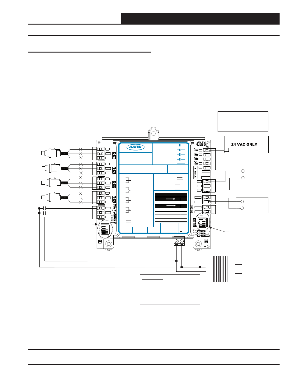
Figure 9: Version 1.06 and Earlier One Condenser Head Pressure Module Wiring Diagram (Stand-Alone)
Stand-Alone Wiring
Versions 1.03 through 1.06 utilize Dipswitch 2 in stand-alone mode
for refrigeration selection. See Tables 9 & 10 for further information.