One condenser head pressure module, Installation & wiring, Technical guide – Orion System One Condenser Head Pressure Module User Manual
Page 7: Alarm, Stat, Comm
Technical Guide
One Condenser Head Pressure Module
7
Installation & Wiring
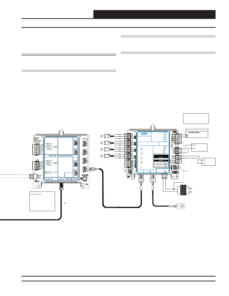
If using a spliced terminal connection for longer runs, one module can be
connected to the E-BUS Distribution Module and any additional modules
would be daisy-chained to the fi rst module. For more information, refer
to the E-BUS Distribution Module Technical Guide.
NOTE: Contact Factory for the correct HSSC cable length for
your application. Cables are available in ¼, ½, 1, 2, 3,
4, and 5 Meter lengths and 100 and 150 Foot lengths.
WARNING: Be sure all controllers and modules are
powered down before connecting or
disconnecting HSSC cables.
Figure 3, cont.: VCM-X WSHP Controller to One Condenser Head Pressure Module Wiring Diagram
WARNING!!
Observe Polarity! All
boards must be wired with
GND-to-GND and 24 VAC-
to-24 VAC. Failure to
observe polarity could
result in damage to the
boards.
OE365-23-EBD E-BUS
Distribution Module
GND
-COMM
SHLD
+COMM
INPUT
+COMM
SHLD
-COMM
GND
+VDC
485 DRV
24VAC
GND
PWR
YS102308
REV 1
I2C TO COMM
DIST. BOARD
OUTPUT
Modular Cable
Connect To
VCM-X WSHP Controller,
VCM-X Modular Controller,
or SA Controller
HSSC Cable
Connect To E-BUS
Distribution Module
Connect To Other
WattMaster-Approved
E-BUS Expansion Module(s)
HSSC Cable
SIG
GND
+V
BK
RD
WH
SIG
GND
+V
BK
RD
WH
SIG
GND
+V
BK
RD
WH
SIG
GND
+V
BK
RD
WH
Head Pressure Transducers
0 - 667 PSI
(One Per Refrigerant Circuit)
OE370-23-HP1C
One Condenser Head Pressure Module
+5V
SIG 2
GND
OP
T
IO
N
S
ALARM
ANALOG
STAT
+5V
COMM
GND
SIG 4
GND
R1
R2
GND
RELAYS
SIG 3
+5V
GND
+5V
SIG 1
R3
R4
Rc
AO1
AO2
PWM1-
PWM1+
PWM2-
PWM2+
PWR
COM
Condenser
Signal
+
24 VAC Transformer
3 VA Minimum
Line Voltage
24 V
A
C
GND
R1
NOTE:
NORMALLY OPEN AND
RATED FOR 24 VAC POWER
ONLY - 1 AMP MAXIMUM LOAD
ALL RELAY OUTPUTS
ARE
COMM
OPTIONS Dip Switch
Setting Not Required
When Connected To
VCM-X Modular or
VCM-X WSHP
Controller
Set ADDRESS Dip
Switch 1 to ON for
Water Cooled or to
OFF for Air Cooled.
Currently showing
OFF for Air Cooled.
Set ADDRESS Dip
Switch 2 to OFF on all
communicating
applications unless it
is intended to be the
Second Head
Pressure Module on a
system. If set to ON, it
will not communicate.
Currently showing
OFF.
Set ADDRESS Dip
Switch 4 to OFF to
make reversing valve
"ON to Heat / OFF to
Cool” Set to ON to
make reversing valve
“ON to Cool / OFF to
Heat. Currently
showing OFF.
ADDRESS
BIN 1
BIN 2
BIN 3
COM
LED BLINK CODES
LED NAME
STAT
BLINKS QTY. OF SENSORS INSTALLED
LED NAME
ALARM
NO PROBLEMS
0
NO SENSORS DETECTED
1
HIGH HEAD PRESSURE DETECTED
2
LOW HEAD PRESSURE DETECTED
3
WattMaster Label
#LB102057-A
Rev.: 1J
E-BUS
Connector
E-BUS
Connector
+5V
SIG 1
GND
+5V
SIG 2
GND
+5V
SIG 3
GND
+5V
SIG 4
GND
+24
VA
C
GND
HEAD
PRESSURE
TRANSDUCER #1/
HEAD
PRESSURE
TRANSDUCER #2
HEAD
PRESSURE
TRANSDUCER #3
HEAD
PRESSURE
TRANSDUCER #4
PWM2+
One Condenser Head Pressure Module
1C
Orion No.:OE370-23-HP
AAON No.:
R74860
AO1
AO2
GND
COND. SIGNAL
NOT USED
PWM1-
PWM1+
PWM2-
COND. FAN
NOT USED
COND. FAN
NOT USED
GND
RELA
Y
CONT
ACT
RA
TING IS 1
AMP
MAX @ 24 V
AC
COND. ENABLE
NOT USED
NOT USED
R1
R2
R3
R4
RC
RELAY COMMON
BIN 1
BIN 2
BIN 3
COM
NOT USED
COMMON
COND. ENABLE INPUT
REV. VLV. INPUT ENABLE
A1
A2
A3
A4
REV. VLV. ENABLE
www.aaon.com
R2
CONDENSER A ENABLE
HVAC UNIT CONNECTIONS
REV. VALVE A ENABLE
+24 Volts
Condenser Fan
ECM Motor
Duty Cycle
YELLOW
BLUE +24 OUT