One condenser head pressure module, Installation & wiring, Technical guide 4 – Orion System One Condenser Head Pressure Module User Manual
Page 4: Environmental requirements, Mounting
One Condenser Head Pressure Module
Technical Guide
4
Installation & Wiring
Environmental Requirements
The One Condenser Head Pressure Module needs to be installed in an
environment that can maintain a temperature range between -30°F and
150°F and not exceed 90% RH levels (non-condensing).
LED BLINK CODES
LED NAME
STAT
BLINKS QTY. OF SENSORS INSTALLED
LED NAME
ALARM
NO PROBLEMS
0
NO SENSORS DETECTED
1
HIGH HEAD PRESSURE DETECTED
2
LOW HEAD PRESSURE DETECTED
3
WattMaster Label
#LB102057-A
Rev.: 1J
E-BUS
Connector
E-BUS
Connector
+5V
SIG 1
GND
+5V
SIG 2
GND
+5V
SIG 3
GND
+5V
SIG 4
GND
+24
VA
C
GND
HEAD
PRESSURE
TRANSDUCER #1/
HEAD
PRESSURE
TRANSDUCER #2
HEAD
PRESSURE
TRANSDUCER #3
HEAD
PRESSURE
TRANSDUCER #4
PWM2+
One Condenser Head Pressure Module
1C
Orion No.:OE370-23-HP
AAON No.:
R74860
AO1
AO2
GND
COND. SIGNAL
NOT USED
PWM1-
PWM1+
PWM2-
COND. FAN
NOT USED
COND. FAN
NOT USED
GND
RELA
Y
CONT
ACT
RA
TING IS 1
AMP
MAX @ 24 V
AC
COND. ENABLE
NOT USED
NOT USED
R1
R2
R3
R4
RC
RELAY COMMON
BIN 1
BIN 2
BIN 3
COM
NOT USED
COMMON
COND. ENABLE INPUT
REV. VLV. INPUT ENABLE
A1
A2
A3
A4
REV. VLV. ENABLE
www.aaon.com
5.04
5.64
5.71
2.07
0.55
4.14
0.29
0.18 DIA. TYP.
ALARM
ANALOG
STAT
COMM
R1
R2
GND
RELAYS
R3
R4
Rc
AO1
AO2
PWM1-
PWM1+
PWM2-
PWM2+
ADDRESS
OPTIONS
+5V
SIG 2
GND
+5V
SIG 3
GND
+5V
SIG 4
GND
+5V
SIG 1
GND
BIN 1
BIN 2
BIN 3
COM
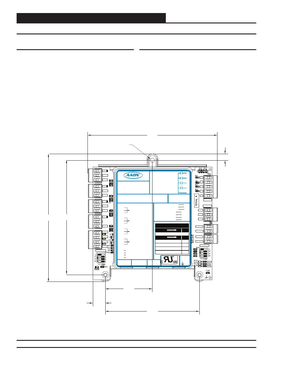
Figure 2: One Condenser Head Pressure Module Dimensions
Mounting
The One Condenser Head Pressure Module is housed in a plastic en-
closure. It is designed to be mounted by using the 3 mounting holes in
the enclosure base. It is important to mount the module in a location
that is free from extreme high or low temperatures, moisture, dust, and
dirt. Be careful not to damage the electronic components when mount-
ing the module.
See Figure 2 for Module dimensions (in inches).