Quantum Composers 9500 Plus Series User Manual
Page 57
53
o
The “Clock Out” BNC connector will output a signal dependent on the current
configuration. If the “Clock In” parameter is enabled, the 10 MHz signal present
on the Clock in BNC will also be present (and synchronized) on the Clock Out
connector. If Clock In is disabled and Clock Out is enabled, the 9500+T will
generate and output a 10 MHz signal intended for synchronizing other
instruments. If the Clock Out parameter is disabled, the system pulse (T ) will
be present on the output BNC connector, showing whatever frequency is being
generated in the current setup.
Mode Menu
To access the Oscillator menu unique to the “T” option instrument, press the
“Function-Mode” key sequence twice. The first set will enter into the standard
channel mode menu, and the second sequence will enter the Clock In/Out menu.
To Mode
Oscillator Menu
System Mode
Oscillator Out Enable
Oscillator In Enable
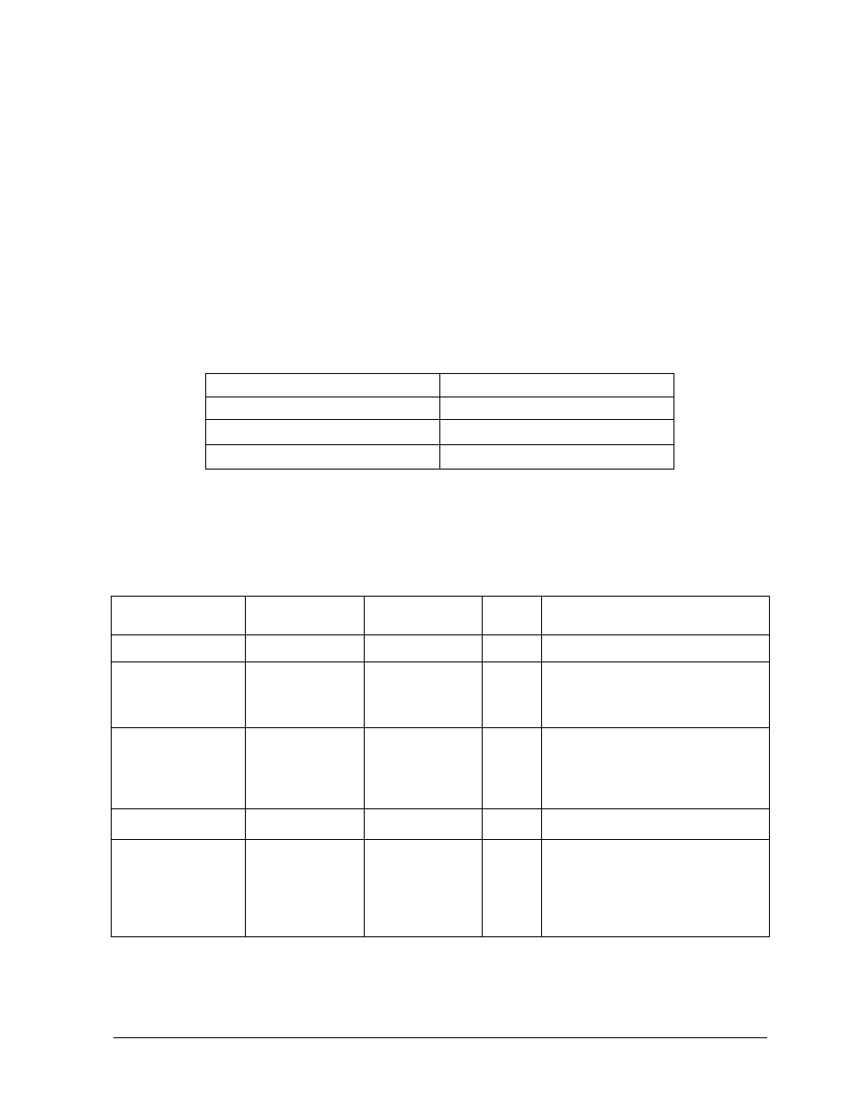
Serial Commands
Keyword
Lower-Level
Keyword
Parameter
Std /
New
Comments
:SPULSe
:ICLock
0 / 1 or OFF / ON
New
Enables / Disables lock to 10 MHz
signal. Can be set to "1" or "0"
(Enable or Disable, respectively).
Query returns "
:OCLock
0 / 1 or OFF / ON
New
Enables / Disables output 10 MHz
signal. Can be set to "1" or "0"
(Enables or Disable, respectively).
Query returns "Enabled" or
"Disabled"
:PULSe [1 / 2n]
:MUX
ENABle / DISable
New
Enables / Disables Multiplexing.
Multiplexing is implemented in
channel pairs. Channel A can be
combined with Channel B, just as
Channel C can be combined with
Channel D, etc.