Channels section – Quantum Composers 9250 Series User Manual
Page 18
9250 Manual Version 1.2 | Quantum Composers
18
Channels Section
The Channels Section of the 9250 application only affects the 9250
’s channel parameters.
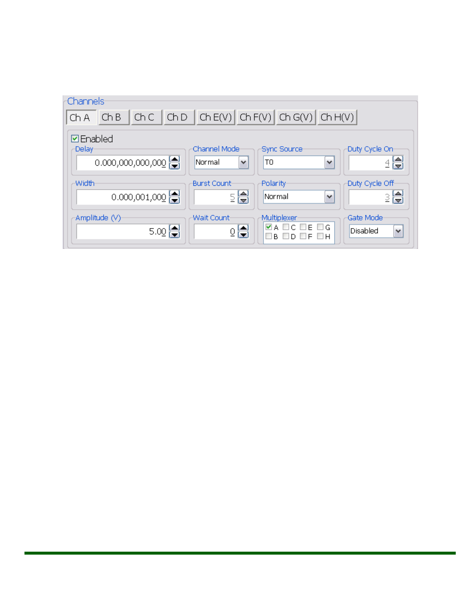
Complex pulse trains can be created by combining various system and channel modes. As
shown below in Figure 6.3, the following channel parameters may be altered:
Figure 6.3
–9250 Application: Channel Parameters
Channel Selection: Select the proper Channel tab in order to further edit the
parameters on the corresponding channel.
Enabled: Enables and Disables the output for the selected channel.
Delay: Sets the delay from the timing reference to when the pulse is created. Valid
input is
±4000s with 5ps increments. Note: negative delays are only applicable if you are
referenced to a channel that has a positive delay.
Width: Sets the pulse width for the selected channel. Valid input is 8ns
– 4000s with
4ns increments.
Amplitude: Allows the user to select the voltage amplitude of the output. Valid values
are 3.3V
– 5V with 20mV increments.
Channel Mode: Changes the Channel Mode to Normal, Single Shot, Burst, or Duty
Cycle.
o Normal: Channel will produce pulses as long as a T
0
is present (mimics System
Pulse Mode)
o Duty Cycle: If Duty Cycle has been selected in the Channels section, the unit will
generate a continuous pulse stream in which outputs will be On for “N” pulses
and Off for “M” pulses. One may alters the “N” (On) and “M” (Off) parameters:
On Counts (“N”): Positive integer value which designates the number of
pulses to produce during the “On Cycle.” Valid inputs are 1-1,000,000.
Off Counts (“M”): Positive integer value which designates the number of
pulses to suppres
s during the “Off Cycle.” Valid inputs are 1-1,000,000.