Analog audio, Synchronization and control, Midi – Teac X-48MKII User Manual
Page 15: Time code, Footswitch, Remote (sony 9-pin), Video reference (tri level sync), 3 – setup
TASCAM X-48MKII
15
THRU
This connector passes the Word Clock signal
present at the Word Clock IN through without
adding any delay. This allows additional devices
to be locked in a daisy-chain fashion in configu-
rations where there is no way to directly distrib-
ute clock from a single source.
Analog Audio
The IF-AN24X provides 24 channels of balanced analog
inputs and 24 channels of balanced analog outputs.
The X-48MKII can be configured to one of five possible
operating reference levels by applying the appropriate
software settings. Please refer to ‘Analog I/O Operating
Level’ (page 20) for details.
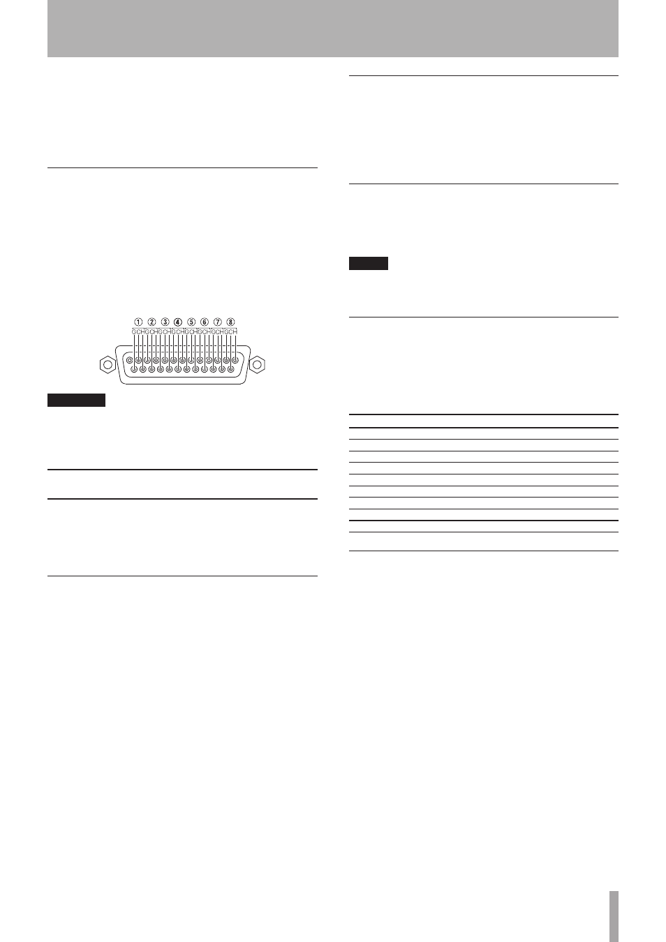
The analog DB-25 pinout is pictured below:
1
14
25
13
CAUTION
Use only DB25 cables specified by the manufacturer as
“Analog” cables. Many cables look the same on
the outside.
Synchronization and Control
This section will deal with the physical connections
needed in various synchronized applications. For details
about the appropriate software settings, please refer to
the ‘Synchronization’ section (page 35).
MIDI
There are two MIDI connectors on the rear of the
X-48MKII. These are used for MIDI Machine Control (MMC)
and MIDI Time Code (MTC).
IN
This connector receives MTC, which the
X-48MKII can chase, or MMC, which the
X-48MKII can respond to. The front panel MIDI
LED will illuminate when valid MIDI signals are
present at this connector.
OUT
This connector outputs MTC any time the
transport is in motion. That MTC output follows
the frame rate and output options set for LTC
output. MIDI machine control (MMC) open loop
and closed loop are supported.
Time Code
There are two 1/4” TRS connectors on the rear of the
X-48MKII, used for sending and receiving time code (LTC).
These connectors are balanced to allow for long cable
runs with minimal interference. Please refer to pages 37-
40 for details on time code options.
Footswitch
A momentary footswitch may be connected to this 1/4”
TS connector for hands free play, stop, and punch-in/out
operation.
NOTE
To operate correctly, a footswitch must be connected
before the X-48MKII is powered on.
Remote (Sony 9-Pin)
This is also known as “P2” or “Sony P2” or “RS-422”. Various
recording consoles and video controllers support this
protocol for transport control and track record enable.
This requires a specifically constructed cable. If in doubt,
pre-made RS-422 cables are readily available.
Pin No.
Controlling end
Non-controlling end
1
GND
GND
2
RX–
TX–
3
TX+
RX+
4
TX common
RX common
5
Spare (NC)
Spare (NC)
6
RX common
TX common
7
RX+
TX+
8
TX–
RX–
9
GND
GND
Video Reference (Tri Level Sync)
IN
When the X-48MKII is used in a film/video post
production environment, it may be necessary
to resolve a consistent sample range with the
time code edge. A video reference (blackburst)
signal applied to this connector makes this
possible. Please refer to page 19 for details on
configuring the use of signals present at this
connector.
Tri Level Sync is the video reference signal used for High
Definition Video. This connector automatically senses the
type of signal present.
THRU
The video reference signal present at the IN
connector is passed through out this
connector without additional processing delay.
This allows for daisy-chaining another device,
after the X-48MKII, which requires a video refer-
ence signal.
3 – Setup