5 – using the us-322/366 mixer panel, Mixer panel settings, Interface” page – Teac US-322 User Manual
Page 17
TASCAM US-322/366
17
5 – Using the US-322/366 Mixer Panel
Press the MIXER PANEL button on the top of the unit to open
the Mixer Panel on the display of the connected computer.
The mixer panel has three pages.
Click on a tab to open the corresponding page.
INTERFACE: View information about the driver status and
connection and make various settings.
MIXER:
Make built-in mixer settings.
EFFECTS: Make built-in effects settings.
Mixer panel settings
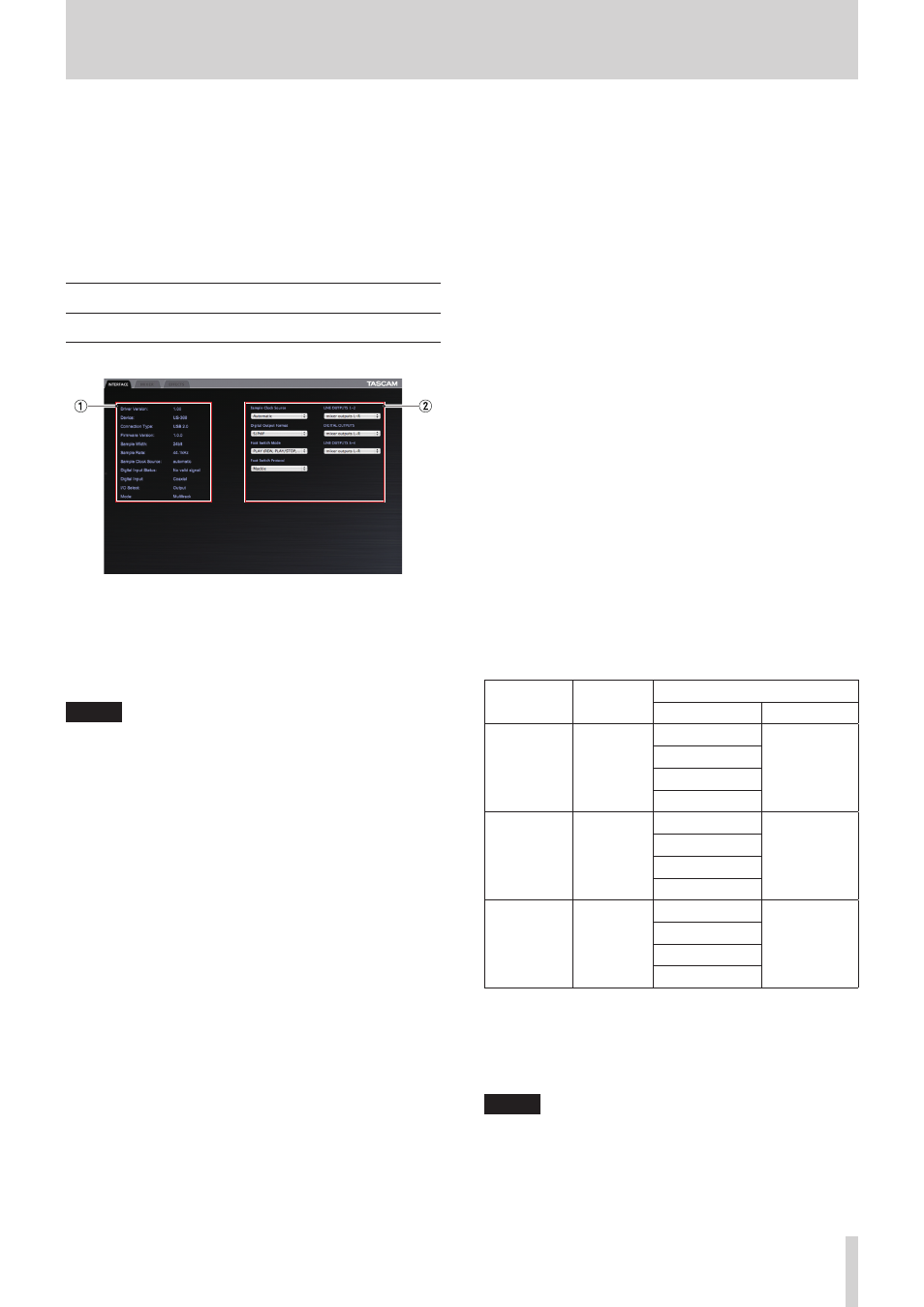
“INTERFACE” page
The “INTERFACE” page appears divided into the following two
sections.
1
Status display section
This shows information about the current driver and the
connected hardware. The current settings of the switches on
the bottom of the unit are also shown.
NOTE
• If the “Digital Input Status” is “Valid Signal”, a valid digital
signal is being input. If it is “No Valid Signal”, no valid digital
signal is being detected. Check the setting of the switch on
the bottom of the unit and confirm that the digital output of
the connected equipment meets the requirements for input
into this unit.
• Settings cannot be made in this section.
2
Setting section
This has various driver settings that can be changed.
Audio Performance
This unit's driver temporarily stores the audio signals input
to and output from the computer in a buffer.
The size of this buffer can be adjusted.
The smaller the size of the buffer, the shorter the audio signal
delay (latency). However, the smaller the size, the greater the
demand on the computer processor. If the audio data cannot
be processed in time due to the demands of other system
operations, for example, clicking and popping noises as well
as audio dropouts and other audio problems might occur.
The larger the buffer size, the more stable the operation,
making the processing of audio signals less likely to be
hindered by other system operations. However, larger buffer
sizes also increase the latency of the audio handled by the
computer.
You can set the buffer size used for this unit according to
your conditions.
When using Windows, adjust the buffer size using its “Audio
Performance” Control Panel. The “lowest latency” setting is
the smallest buffer size, while the “highest latency” setting is
the largest.
When using Mac OS X, you can adjust the buffer size for each
audio application that you are using. For this reason, there
is no “Audio Performance” control panel in Mac OS X. For
details, see the operation manual for the audio application
that you are using.
Sample Clock Source
You can set the clock source to “Automatic” or “Internal”. Set
it to “Automatic” if you are using a digital input.
When set to “Automatic”, the “Sample Clock Source” will
automatically switch to “Digital” when there is a digital input
and switch to “Internal” (internal clock) when there is no
digital input.
• Automatic (default): If a clock signal is input through the
DIGITAL IN jack, it is used. If no signal is input through
the DIGITAL IN jack, this unit’s internal clock is used.
• Internal: This unit’s internal clock is always used.
Digital Output Format
Set the digital output format to “S/PDIF” or “AES/EBU” .
LINE OUTPUTS and DIGITAL OUTPUTS (output
selection)
US-322
This model outputs two signal channels.
Use the “LINE OUTPUTS 1-2” item to set the signal output
from the LINE OUT 1/L and 2/R jacks to either “mixer
outputs L-R” or “computer 1-2”.
US-366
This model outputs up to six signal channels. The options
available depend on the settings of the LINE I/O and
MODE switches on the bottom of the unit. Refer to the
following table for a summary of the available options.
Setting item
Output
(connector)
MODE***
MILTITRACK
STEREO MIX
LINE
OUTPUTS
1-2
LINE OUT
1/L, 2/R
mixer outputs L-R mixer outputs
L-R
computer
1-2
computer 1-2
computer 3-4
computer 5-6**
DIGITAL
OUTPUTS
DIGITAL
OUT
mixer outputs L-R mixer outputs
L-R
computer
1-2
computer 1-2
computer 3-4
computer 5-6**
LINE
OUTPUTS
3-4*
LINE OUT
3, 4
mixer outputs L-R mixer outputs
L-R
computer
1-2
computer 1-2
computer 3-4
computer 5-6**
*Usable only when the LINE I/O switch on the bottom of the
unit is set to INPUT.
**Selectable only when the LINE I/O switch on the bottom of
the unit is set to OUTPUT.
***Set using the MODE switch on the bottom of the unit.
NOTE
If you want to output Windows Media Player or iTunes, for
example, through this unit’s DIGITAL OUT, set the “DIGITAL
OUTPUTS” to “computer 1-2” in the Control Panel.