Rear panel, 2 − names and functions of parts – Teac US-322 User Manual
Page 9
TASCAM US-322/366
9
2 − Names and Functions of Parts
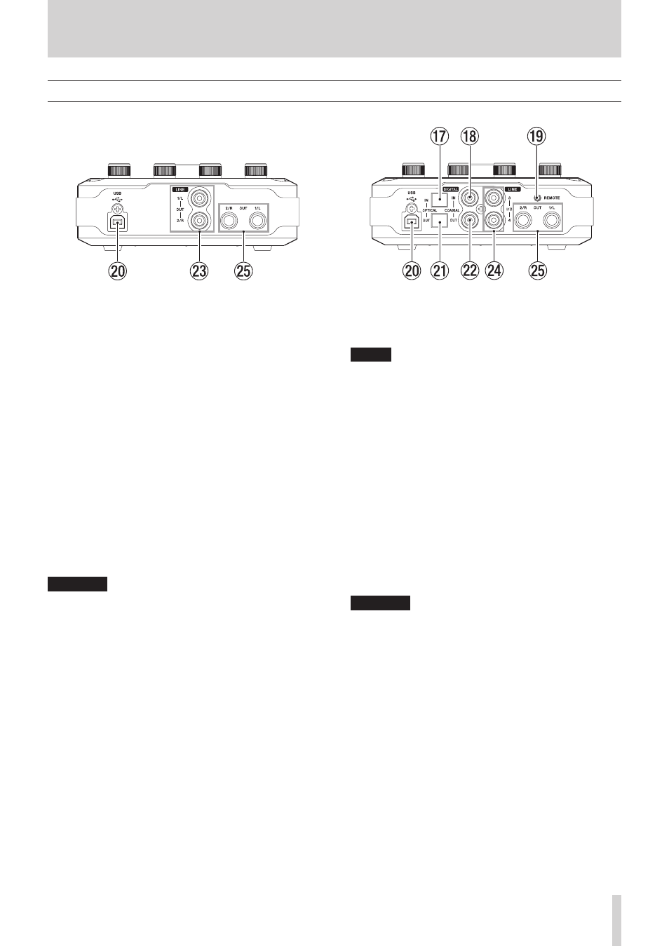
Rear panel
US-322
US-366
u
DIGITAL IN OPTICAL connector (US-366 only)
This optical digital input connector complies with the S/PDIF
(IEC 60958 consumer) standard.
Signals cannot be simultaneously input through this
connector and the DIGITAL IN COAXIAL jack.
Set the DIGITAL IN switch on the bottom of the unit to
OPTICAL to use this connector.
i
DIGITAL IN COAXIAL jack (US-366 only)
This coaxial digital input connector complies with the S/PDIF
(IEC 60958 consumer) standard.
Signals cannot be simultaneously input through this jack
and the DIGITAL IN OPTICAL connector.
Set the DIGITAL IN switch on the bottom of the unit to
COAXIAL to use this connector.
o
REMOTE jack (US-366 only)
Connect a TASCAM RC-3F foot switch remote control (sold
separately) to this 2.5mm TRS mini jack. When a foot switch
is connected, you can operate the transport in applications
that support Mackie control or HUI protocols.
p
USB port
Use the included USB cable to connect this unit with a
computer (supports USB 2.0).
CAUTION
• USB 1.1 is not supported.
• This is not compatible with computer Suspend (Sleep) mode.
For this reason, the unit might not operate properly after a
connected computer is brought out of Suspend (Sleep). In
this case, disconnect the USB cable once and then reconnect
it.
a
DIGITAL OUT OPTICAL connector (US-366 only)
This optical digital output connector complies with the S/
PDIF (IEC 60958 consumer) and AES/EBU (IEC 60958 pro)
standards.
s
DIGITAL OUT COAXIAL jack (US-366 only)
This coaxial digital output connector complies with the S/
PDIF (IEC 60958 consumer) and AES/EBU (IEC 60958 pro)
standards.
NOTE
• The US-366 COAXIAL IN/OUT jacks support simultaneous
24-bit /192kHz input and output.
• The US-366 DIGITAL IN connectors include an OPTICAL and
a DIGITAL input, but they cannot both be used at the same
time. Use the DIGITAL IN switch on the bottom of the unit to
set which is active.
• The US-366 has two DIGITAL OUT connectors. Both the
OPTICAL connector and the COAXIAL jack can be used
simultaneously for digital output. The same signal is output
from both.
d
LINE OUT 1/L and 2/R jacks (unbalanced) (US-322 only)
These RCA pin jacks are analog line outputs.
These output the same signals as the balanced LINE OUT 1/
L and 2/R jacks.
f
LINE I/O 3 and 4 jacks (unbalanced) (US-366 only)
These RCA pin jacks can be used for analog line input or
output. Use the LINE I/O switch on the bottom of the unit to
set whether they are used for input or output.
CAUTION
When the LINE I/O switch is set to OUTPUT and the unit
is operating with a 176.4/192kHz sampling frequency,
regardless of the setting on the “INTERFACE” page of the
Mixer Panel, the DIGITAL OUT signal will also be output
from the LINE IN-OUT 3/4 jacks.
g
LINE OUT 1/L and 2/R (balanced) jacks
These standard TRS jacks are analog line outputs (tip: HOT,
ring: COLD, sleeve: GND).
These output the same signals as the unbalanced LINE OUT
1/L and 2/R jacks. (US-322 only).