Tri Tool 614RBL Thru 636RBL Clamshells User Manual
Page 33
33
Model 614RBL thru 642RBL Clamshells
92-0480 : Rev. 130916
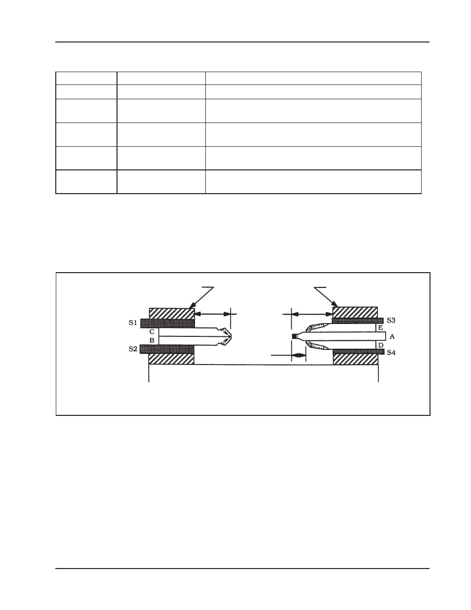
Figure: 19.
Tool Bit Installation
Headstock
Tool Block No. 1
Tool Block No. 2
.50"
(12.7 mm)
Pipe Wall
Thickness
plus .75"
(19.1 mm)
6.8 TOOL BIT DESCRIPTION
Tool Bit
Type of Bit
Function
A
Sever
Creates a straight cut to separate the pipe
B
Bevel
Shapes the edge of the pipe so it forms an angle
other than an right angle.
C
Clearance
Removes part of the pipe before the bevel bit is
used.
D
Bevel
Shapes the edge of the pipe so it forms an angle
other than an right angle.
E
Bevel
Shapes the edge of the pipe so it forms an angle
other than an right angle.
6.9 TOOL BIT ADJUSTMENT FOR STRAIGHT AND DOUBLE BEVEL
CUTS
1. Install Tool Bits A, D and E into Tool Block No. 1 along with Adjustable Bars,
S3 and S4. You can designate either Tool Block as No. 1.
2. Position the Spacers flush with the inside face of the Tool Holder.
3. Position Tool Bits D and E approximately 1/2” (12.7 mm) outward from the
cutting edge of Tool Bit A.
4. Reposition Tool Bits D and E to contact the beveled surface as the cutting
progresses.
5. Tighten the Set Screws holding Tool Bits A, D and E.
6. Install the Tool Bits B and C into Tool Block No. 2 along with the two
Spacers, S1 and S2.
7. Position the Spacers flush with the inside face of the Tool Holder.
8. Ensure that Tool Bits B and C are same distance inward from the Tool Holder.
9. Tighten the Set Screws holding Tool Bits B and C.
10. Set Tool Bit A to lead Tool Bit B and C by the desired land width as follows: