Tri Tool 614RBL Thru 636RBL Clamshells User Manual
Page 34
34
TRI TOOL INC.
92-0480 : Rev. 130916
11. Rotate the Headstock slowly. While rotating the Headstock, determine the
point on the surface where Tool Bit A comes closest to the pipe.
12. Rotate the Feed Sprocket until Tool Bit A makes contact with the pipe.
13. Back the Tool Holder away from the pipe about 1/2 of a revolution.
(Approximately .008” [.20 mm]) This ensures that the equipment does not
start rotating with the tool bit in a cut.
14. Each full revolution of the Feed Sprocket moves the Tool Bit .015” (.38 mm)
toward or from the pipe.
15. Continue to slowly rotate the Headstock through 360°, to verify that the
position of Tool Bit A allows .008” (.20 mm) minimum clearance between Tool
Bit A and the pipe surface at the closest point.
16. Readjust Tool Bit A if necessary.
17. Mark the pipe surface to define the closest approach of Tool Bit A to the pipe.
18. Continue to slowly rotate the Headstock.
19. Position Tool Bits B and C above the mark that you made to define the closest
approach of Tool Bit A to the pipe.
20. Rotate the Feed Sprocket until Tool Bits B and C contact the pipe.
21. Back the Tool Holder off 1/2 a revolution of the Feed Sprocket until Tool Bits B
and C make contact with the pipe surface.
22. Back the Tool Holder off 1/2 a revolution of the Feed Sprocket (approximately
.008” [.20 mm]) plus the desired land width. Each revolution of the Feed
Sprocket moves the Tool Bit .015” (.38 mm) toward the pipe.
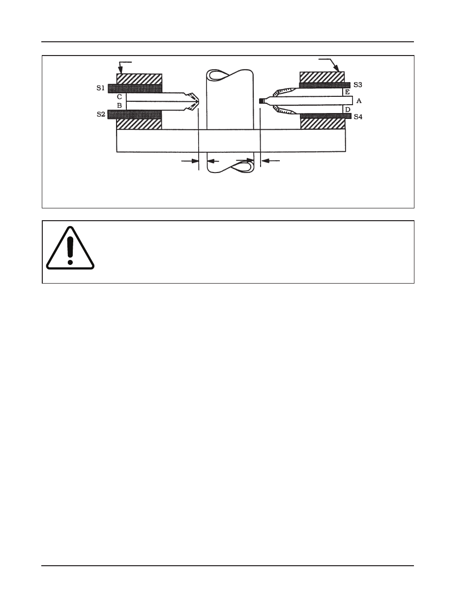
.008"
(.20 mm)
Figure: 20.
Tool Bit Set-Up for Land Width
Headstock
pipe
Tool Block No. 2
.008"
(.20 mm)
plus land width
Tool Block No. 1
CAUTION
CAUTION: Ensure that the Tripper Shaft is in the 'Out' position.