Verilink PRISM 4151 (34-00258) Product Manual User Manual
Page 11
Installation 2-3
PRISM 4151
Before connecting the PRISM 4151 to the LAN network,
configure the LAN interface using the SNMP Parameters
screen (page 3 -7) of the unit firmware.
Connection to an IBM Type 1 cable requires a TxPORT
adapter kit (part number 9-1001-072-1). This kit includes an
impedance matching adapter.
SLIP
The SLIP port is an 8-pin modular jack (electrically RS-
232) DCE port configured for 8 bits, no parity, and 1 stop
bit. The bit rate defaults to 19200 bps but may be changed
through the terminal interface (see Management Ports on
page 3 -8). Figure 2-5 provides the pinout assignments. See
page 1 - 3 for cable information.
This port allows access to the embedded SNMP agent for
trap reporting or SNMP management. You may access this
port through either a direct connection or a dial-up connec-
tion via an AT command set compatible modem. Serial bit
rates can be set from 1200 bps to 19200 bps.
Direct Connection: The SLIP port is connected to a termi-
nal server or router that provides SLIP access to the LAN.
The TCP /IP connection is ‘always up’ in this mode.
Dial Connection: In this mode, a modem is connected to
the SLIP port allowing you to initiate a SLIP connection to
the CSU/DSU from remote sites whenever access is desired.
The modem should be configured to ignore DTR, enable
auto answer, inhibit command echo, and return verbose
result codes. Also, when the CSU/DSU has alarm messages
to transmit, it dials out of the port using the phone number
programmed in the Management Ports screen (page 3-8).
When a connection is made, the CSU/DSU outputs the
ASCII characters stored in its buffer. If a phone number is
not programmed, the CSU/DSU never dials out but you can
dial in. The IP Connection must be changed to the SLIP port
in the ‘TCP/IP’ screen (page 3-6). The SLIP and LAN port
cannot both be active at the same time.
SUPV
The SUPV port is an 8-pin modular jacks (electrically RS-232)
DCE port configured for 8 bits, no parity, and 1 stop bit. The
SUPV port bit rate is fixed at 19200 bps. Figure 2-5 provides
the pinout assignments. See page 1 - 3 for cable information.
The COA feature works through the supervisory port only.
You can configure the unit firmware through this port (page
3-2) as well as the Call On Alarm feature (page 3-8). You
may access this port through either a direct VT100 connec-
tion or a dial-up connection via an AT command set compat-
ible modem. The modem should be configured to ignore
DTR, enable auto answer, inhibit command echo, and return
verbose result codes.
If you call the unit and send the BREAK com-
mand before receiving the CONNECT message,
the modem will hang-up.
Table 2-E Token Ring Pinout Assignments
Pin
Token Ring Interface
3
Data Out (-)
4
Data In (+)
5
Data In (-)
6
Data Out (+)
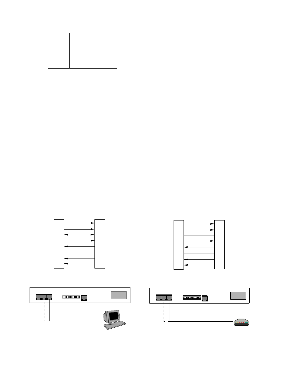
Figure 2-5 SUPV and SLIP Terminal/Modem Connections
PRISM 4151 Rear Panel
PRISM 4151 Rear Panel
PC
Modem
RS-232 to Modem
RS-232 to Terminal
DCD Out
1
CTS Out
2
Frame Gnd
3
Data Out
4
Data In
5
Signal Gnd
6
RTS
In 7
DTR
In 8
PC (DTE)
S
UPV
/S
LIP
Port
1 DCD
8
CTS
5
Frame Gnd
2
RXD
3
TXD
NC Signal Gnd
7
RTS
4
DTR
8-Pin
DB-9
PN# 9-1001-073-2
PN# 9-1001-083-1
Modular
DTR Out
1
RTS Out
2
Frame Gnd
3
Data Out
4
Data In
5
Signal Gnd
6
CTS
In 7
DCD
In 8
Modem (DCE)
S
UPV
/S
LIP
Port
20 DTR
4
RTS
1
Frame Gnd
2
TXD
3
RXD
7
Signal Gnd
5
CTS
8
DCD
8- Pin
DB-25
Modular