Configuration, Hardware configuration, Switch s1 – Verilink PRISM 4151 (34-00258) Product Manual User Manual
Page 13: Switch s2
Configuration 3-1
PRISM 4151
3. Configuration
The PRISM 4151 can be configured through manual switch
settings and/or through a VT100 terminal connection to the
supervisory port.
All default options in this manual are underlined.
Hardware Configuration
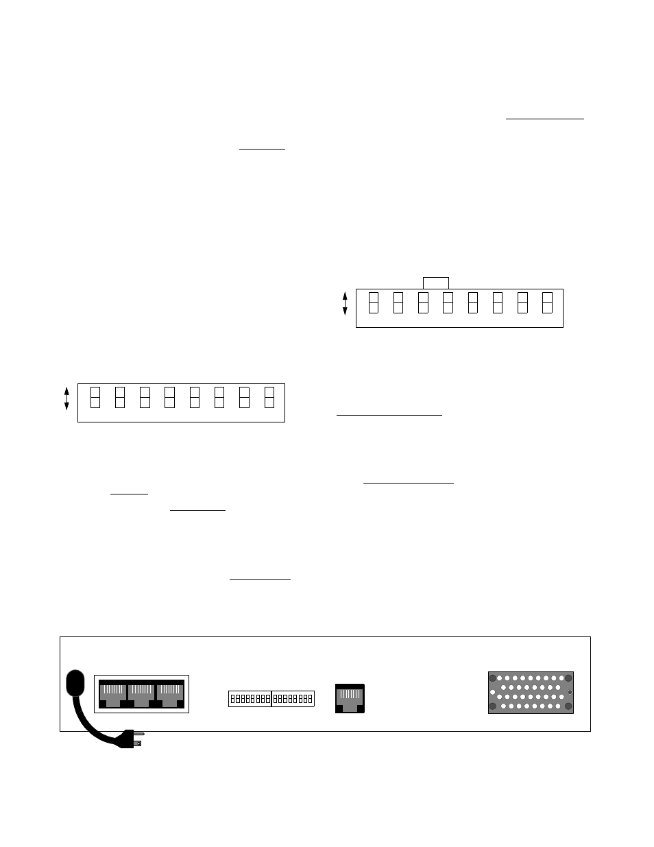
Hardware configuration is set using two dual in-line pack-
age (DIP) switches located on the rear of the unit. These
switches allow you to configure simple applications. Refer
to Figure 3 -6 for switch locations. A removable configura-
tion guide (45-00105) is included in the back of this manual.
Switch S1
Switch S1 (Figure 3-7) configures the antistream timer,
V.54 loop, circuit assurance, and loop mode.
Antistream Timer: Switch S1-1 allows the DDS transmit-
ter to send DMI (Data Mode Idle / all ones) if the RTS
remains enabled long enough for a timeout to occur.
Choices are Off (Dn) or 30 seconds (Up).
V.54 Loop: Switch S1-2 enables (Dn) or disables (Up) the
unit’s ability to respond to incoming V.54 loop/unloop code.
If set to enable, the PRISM 4151 will loop or unloop. If set
to disable, loop codes are ignored.
Circuit Assurance: Switch S1-3 configures the CTS/RTS
sequence. When Circuit Assurance is disabled (Dn), CTS
follows RTS. When enabled (Up), CTS follows RTS if DCD
is also enabled (or set to On).
Loop Mode: Switch S1-4 determines the loop direction for
the transmit and receive data as either bidirectional (Dn) or
unidirection (Up). Refer to page 4 -1 for more information
concerning the loop modes and with respect to testing.
Switch S2
Switch S2 (Figure 3-8) configures the boot mode, DDS
mode, timing source, CTS delay, RTS, CTS, DCD hand-
shake, remote/local loopback, and DTR alarm.
Boot Mode: Switch S2-1 determines whether the unit con-
figures itself from the DIP switches or from the saved soft-
ware configuration. If set to boot from saved software
configuration (Up), the switch settings are ignored. If set to
boot from switches (Dn), the unit reads the DIP switches on
power-up and configures accordingly. Once running, config-
uration changes can be made through the terminal interface,
overriding the switch settings.
DDS Mode: Switch S2-2 establishes the DDS mode as
either DDS II/64 kbps (Dn) or DDS I/56 kbps (Up).
Timing Source: Switch S2-3 and S2-4 determine the unit
clocking source. The most common timing source for CSU/
DSU applications is the network. The PRISM 4151 may
also be optioned to time from an internal standard or from
the high speed data interface as shown in Table 3-H.
SUPV
SLIP
LAN
NET
V.35
115 VAC
60 HZ
S2
S1
Figure 3 -6 PRISM 4151 Rear Panel
7
6
5
4
3
2
1
8
V
.54 L
o
o
p
Circu
it
Ass
u
ran
ce
Dn
Up
Loo
p
Mo
de
Switch
S1
An
ti
strea
m
T
imer
Not Used
Not Used
Not Used
Not Used
Figure 3-7 Switch S1
7
6
5
4
3
2
1
8
D
D
S
M
o
d
e
T
im
in
g
R
em
o
te
/L
o
ca
l
D
T
R
A
la
rm
L
o
o
p
b
ac
k
C
T
S
D
e
la
y
S
o
u
rc
e
D
n
U
p
R
T
S
,
C
T
S
,
D
C
D
H
an
d
sh
ak
e
Switch
S2
Figure 3-8 Switch S2
B
o
o
t
M
o
d
e