Verilink PRISM 4151 (34-00258) Product Manual User Manual
Page 16
3-4 Configuration
PRISM 4151
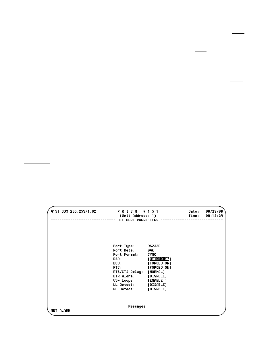
DTE P
ORT
P
ARAMETERS
The DTE Port Configuration screen (Figure 3-11) allows
you to configure the DTE port.
Port Type: The Port Type field displays the active DTE
interface which will be either V.35 or RS-232 (if option is
installed). The active port is automatically detected on
occurrence of transmit data pulses.
Port Rate: Port Rate is determined by the Data Mode selec-
tion on the Network Parameters screen. The values are 56K
for DDS I and 64K for DDS II.
Port Format: This field shows the data format for the DTE
port which is always synchronous.
DSR: This field controls the behavior of the DSR signal
during test modes. If TEST>OFF is selected, DSR will tran-
sition to the Off state when a loop or BERT test is active.
Options are FORCED ON or TEST>OFF.
DCD: This field controls the behavior of the DCD signal
during an IDLE condition. When Data Mode Idle codes are
received, DCD will transition to Off if this field is set to
IDLE>OFF. This only applies to DDS I mode. Options are
FORCED ON or IDLE>OFF.
RTS: If this field is set to NORMAL, the RTS signal will
control the transmitter and CTS output signal. If set to
FORCED ON, the RTS input signal is set to On inside the
unit.
RTS/CTS Delay: This field selects the delay from the RTS
transition (to On) to the CTS transition. The delays are:
NORMAL =0.4 ms +/- 0.02 ms for DDS I
0.3 ms +/- 0.015 ms for DDS II
LONG =
0.8 ms +/- 0.04 ms for DDS I
0.6 ms +/- 0.03 ms for DDS II
DTR Alarm: This option allows you to enable or disable an
alarm if the DTR signal from the DTE device goes false.
V54 Loop: This field controls response to incoming V.54
loop/unloop codes. If set to enable, the PRISM 4151 will
loop or unloop. If set to disable, loop codes are ignored.
LL Detect: This option allows you to enable or disable the
local loop activation by the local loopback signal (V.35 pin J
or RS-232 pin 18) on the DTE interface.
RL Detect: This option allows you to enable or disable the
remote loop activation by the remote loopback signal (V.35
pin BB or RS-232 pin 21) on the DTE interface. Remote
loopback causes transmission of V.54 loop or unloop codes
to the far end device.
Figure 3 -11 DTE Port Parameters Screen