Verilink PRISM 4151 (34-00258) Product Manual User Manual
Page 26
4-2 Testing
PRISM 4151
Clear Tests: Pressing <return> on this field clears all local
tests and any line loops that have been initiated.
Clear Alarms: Pressing <return> on this field causes all
near end alarms to be cleared.
Loop: The type of loop is chosen by toggling the <space-
bar> and is executed by pressing <return>. Options include
LOCAL, V.54, and FAR V.54. Local and V.54 generate near
end loops. Far V.54 generates a V.54 loop at the far end.
Unloop: Pressing <return> takes down the specified loop
from the currently selected port. The type of loop is chosen
by toggling the <spacebar> and is executed by pressing
<return>. Options include LOCAL, V.54, and FAR V.54.
Loop Mode: Options include BIDIRECTIONAL and UNI-
DIRECTIONAL. When set to Unidirectional, the NET
receive data is looped back to the NET as NET transmit data
and continues to pass through the data port to the DTE.
Transmit data from the DTE is terminated. When set to
Bidirectional, the NET receive data is looped back to the
NET as NET transmit data. Transmit data from the DTE is
looped back through the data port as receive data to the
DTE.
Line Loop: Occurs at the DDS network interface and acti-
vated by the reversal of the simplex, 20 mA sealing current.
This is a unidirectional loop that ignores the CSU/DSU
transmit data and retransmits the received DDS data.
Receive data is unaffected and circuits DSR and CD are
forced OFF.
Data Loop: Occurs at the DDS network interface. In DDS I
mode, the data loop is activated when the CSU/DSU
receives alternating loop codes in the network receive data
stream. Technically, it is activated by the receipt of at least 4
consecutive loop commands and remains looped as long as
each 3rd pattern byte is the loop command. It returns to nor-
mal operation after at least 4 pattern bytes that are not the
loop command. This is a unidirectional loop that retransmits
the CSU/DSU received data on the CSU/DSU transmit data
including the remapped loop code. Receive data is unaf-
fected (but includes the modified loop codes) and circuits
DSR and CD are OFF.
In DDS II mode, the data loop is activated when the latching
loopback sequence is received. The sequence consists of 35
or more TIP bytes, 35 or more LSC bytes, 100 or more LBE
bytes, 32 or more FEV bytes. Latching loop is deactivated
when 31 or more TIP bytes are received.
V.54 Loop: Occurs at the DDS network interface and is
activated upon receipt of inband V.54 loop codes for at least
two seconds followed by all ones in the network receive
data stream. This loop is unidirectional and returns the
CSU/DSU receive data to the CSU/DSU transmit data, and
subsequently the DDS transmit data. Receive data is unaf-
fected and DSR and DCD are forced OFF.
Local Loop: Bidirectional and occurs at the DDS network
interface. It returns the DDS receive data to the DDS trans-
mit line and the CSU/DSU transmit data to the CSU/DSU
receive data output.
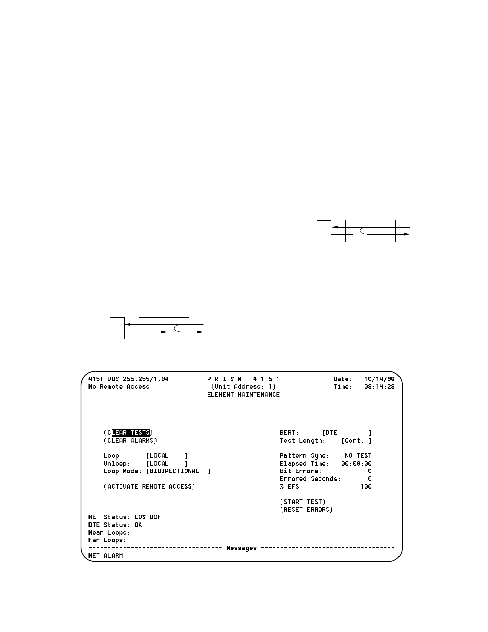
Figure 4 -2 Element Maintenance Screen
DTE
NET
Line Loop
DTE
NET
Data Loop
V.54 Loop