Varmeca - 20, Variable speed motor or geared motor, 3 - connections – Watson-Marlow Varmeca User Manual
Page 27: 3 - adjusting the mini dip switches, 1 - wiring precautions, 2 - terminal blocks, Leroy-somer
25
INSTALLATION AND MAINTENANCE
VARMECA - 20
Variable speed motor or geared motor
CONNECTIONS
LEROY-SOMER
Réf. 3481 - 4.33/c - 09.01
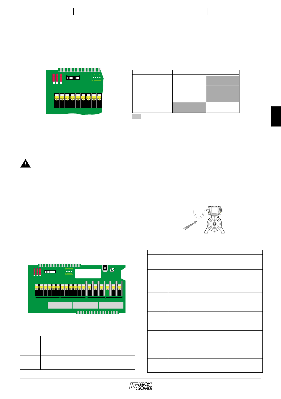
2.3 - Adjusting the MINI DIP switches
These switches are used to select the reference, the U/F ratio and the reference on the analogue input of terminal 2 (see
VARMECA - 20 parameter-setting manual).
Factory settings
CAUTION:
These operations should only be performed in exceptional circumstances and must be carried out by experienced and
qualified personnel.
MINI DIP
OFF
ON
K1
4 - 20mA
0 - 10V
Speed reference
reference
reference
K2
4 - 20mA
0 - 10V
Analogue input
terminal 2
K3
U/F ratio
U/F ratio
U/F ratio
factory setting
constant
ON
K3 K2
P2
P1
P3
K1
OFF
1
2
3
4
5
6
7
8
9
3 - CONNECTIONS
• The voltages on the power terminal blocks and
the cables connected to them may cause fatal
electric shocks. The drive stop function does not
protect against these high voltages.
• The drive contains capacitors which remain
charged at a fatal voltage even after the power supply has
been switched off.
• After switching off the drive, wait for 2 min so that
the internal circuits can discharge the capacitors, before
removing the protection (for the single-phase range).
• The drive power supply must be protected
against overloads and short-circuits.
• It is vital to respect the rating of protection
devices.
• Connection with copper conductor only.
3.1 - Wiring precautions
- When the VARMECA - 20 is controlled remotely, avoid
parallel routing of power cables and control cables.
- All remote control cables must be shielded and have a
cross-section between 0.22 mm
2
and 1 mm
2
. The shielding
should be connected to earth at both ends.
- Check that the different earth points are actually at the same
voltage.
- Incorporate a bend where the cables enter the cable glands
so that water cannot penetrate the terminal box.
- Tighten the cable glands firmly.
en
3.2 - Terminal blocks
3.2.1 - Layout
3.2.2 - P1 terminal block
Standard configuration
Marking
Functions - Characteristics
Connection of protected mains supply phases
L1, L2
200V to 240V ± 10 %, 50-60Hz in single-phase
L1, L2, L3 200V to 480V ± 10%, 50-60Hz in 3-phase
PE
Earth connection
R1, R2
Connection of the braking resistor
Min. resistance value = 180 Ohms
ON
K3 K2
P2
P1
P3
K1
OFF
1
2
3
4
5
6
7
8
9 10 11 12
L1
L2
L3
PE
R+
R-
Control/Command
Mains
M/N :
77b3000A
P/N :
VARMECA21
S/N :
20106000748
1
Locking logic input
Terminals 1 and 3 not connected: drive disabled
Terminals 1 and 3 connected: drive enabled
2
Analogue speed output 0 to +10V, 3mA
0V = zero speed
10V = maximum speed
Analogue input (see VARMECA - 20
parameter-setting manual)
3
Source +24V, 30mA (± 10%)
Common at terminal 10
4
Source +10V, 30mA (± 10%)
5
0V - Connected to the terminal block earth
6
Reference input 0 to +10V or 4-20mA
0-10V: input impedance = 100 kOhms
4-20mA: input impedance = 0.5 kOhms
7
Reverse/Stop logic input
8
Forward/Stop logic input
9
Ramp selection logic input
1s (for 0 at 50Hz) : terminals 9 and 10 not connected
3s (for 0 at 50Hz): terminals 9 and 10 connected
10
Source +24V - 30mA
Common at terminal 3
11, 12
Fault relay - volt-free contact 250V 1A
Contact open: switched off or faulty
Contact closed: in run status
Marking
Functions - Characteristics
INSTALLATION & CONNECTIONS