Varmeca - 20, Variable speed motor or geared motor, 3 - radio-frequency interference – Watson-Marlow Varmeca User Manual
Page 28: 4 - description of cables and protection devices
26
INSTALLATION AND MAINTENANCE
VARMECA - 20
Variable speed motor or geared motor
CONNECTIONS
LEROY-SOMER
Réf. 3481 - 4.33/c - 09.01
3.2.3 - P2 connector
This is used to connect options with control knob (B),
integrated Run/Stop (BMA), integrated Forward/Reverse/
Stop (BMAVAR), etc.
3.2.4 - RS232 serial link type P3 connector
This is used to connect the CDC VMA 20 console or a PC in
order to use the PEGASE VMA 20 programming software or
fieldbus option cards.
3.3 - Radio-frequency interference:
3.3.1 - General
Variable speed drives use high-speed switches (transistors,
semi-conductors) which switch high voltages (around 550V
for 3-phase drives) at high frequencies (several kHz). This
provides better efficiency and a low level of motor noise.
As a result, they generate radio-frequency signals which may
disturb operation of other equipment or distort measurements
taken by sensors:
- due to high frequency leakage currents which escape to
earth via the stray capacity of the drive/motor cable and that
of the motor via the metal structures which support the motor
- by conduction or feedback of R.F. signals on the power
supply cable: conducted emissions
- by direct radiation near to the mains supply power cable or
the drive/motor cable: radiated emissions
These phenomena are of direct interest to the user.
The frequency range concerned (radio-frequency) does not
affect the energy distribution company.
3.3.2 - Standards (Emission)
The maximum emission level is set by the generic industrial
(EN 50081-2) and domestic (EN 50081-1) standards.
VARMECA - 20 conforms to the following standards:
- EN 50081-2 as standard
- EN 50081-1 with filter option (FLT VMA 21M)
3.3.3 - Standards (Immunity)
The maximum immunity level is set by the generic industrial
(EN 50082-2) and domestic (EN 50082-1) standards.
VARMECA 20 conforms to the following standards:
- EN 50082-2 and EN 50082-1 as standard
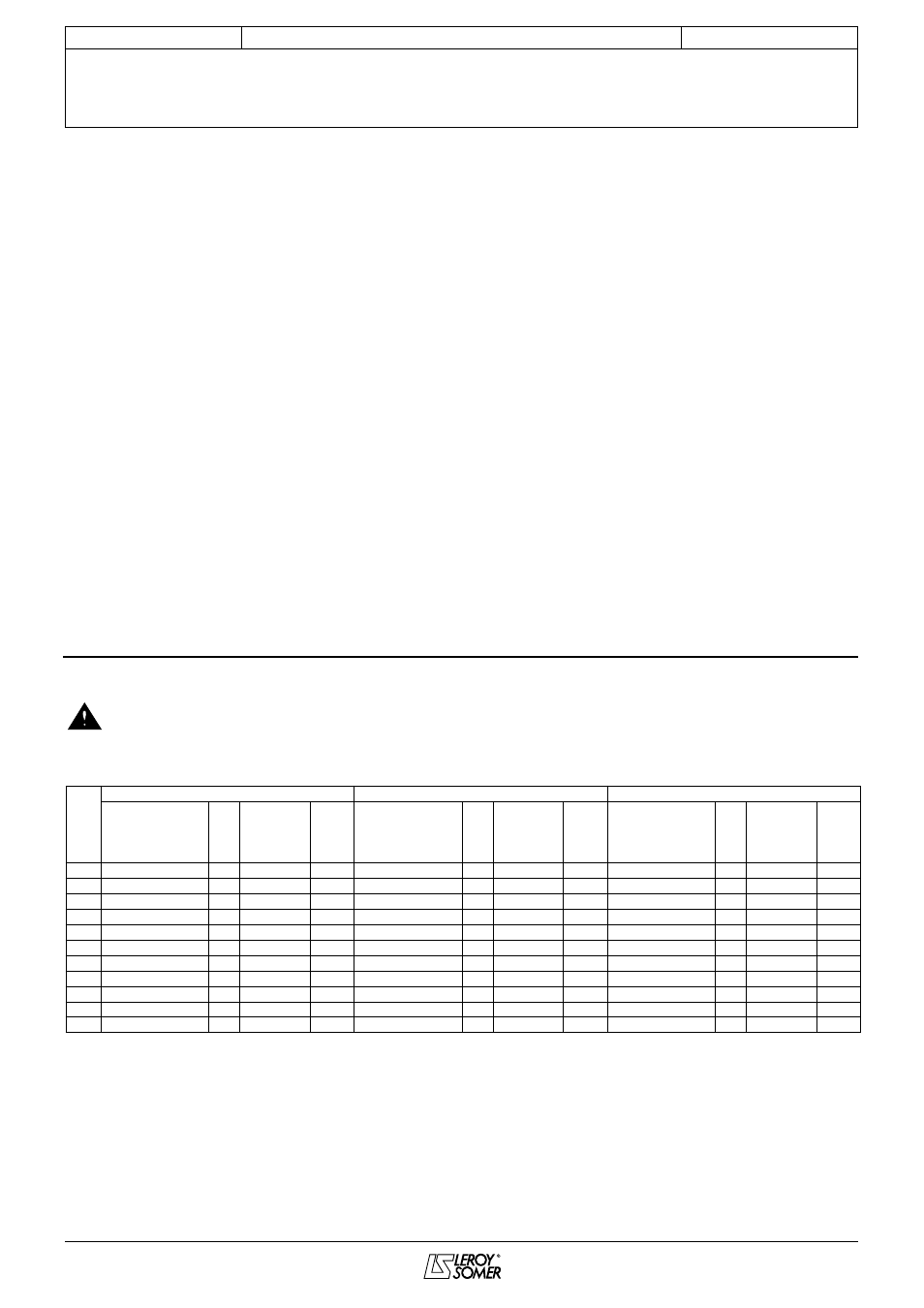
3.4 - Description of cables and protection devices
• When using a circuit-breaker, it must be a motor circuit-breaker (D curve).
• Comply with the size of protection fuses.
• The cable size may vary according to legislation applicable in the country, which will take precedence over the
values given in the table below without exception.
• These tables should never be used instead of current standards.
Note:
• The mains current value is a typical value which depends on the source impedance. The higher the impedance, the lower the
current.
• The fuses (UL approved) are intended for installations capable of delivering 5000A maximum at 480V.
P
(kW)
230V single-phase power supply
230V 3-phase power supply
400V 3-phase power supply
VMA rating
I
gI fuses or
Cables
VMA rating
I
gI fuses or
Cables
VMA rating
I
gI fuses or
Cables
circuit-
circuit-
circuit-
breaker
breaker
breaker
(A)
(A)
(mm
2
)
(A)
(A)
(mm
2
)
(A)
(A)
(mm
2
)
0.25 A or B 21M-025 3.5
8
1.5
A or B 21TL-025
2
4
1.5
A or B 21T-025
1
4
1.5
0.37 A or B 21M-037
4
10
1.5
A or B 21TL-037
3
6
1.5
A or B 21T-037
1.5
4
1.5
0.55 A or B 21M-055 4.5
10
1.5
A or B 21TL-055
4
6
1.5
A or B 21T-055
2
6
1.5
0.75 A or B 21M-075
7
16
2.5
A or B 21TL-075
5
8
1.5
A or B 21T-075
3
6
1.5
0.9
A or B 22M-090
9
16
2.5
A or B 22TL-090 5.5
10
1.5
A or B 21T-090
3.5
8
1.5
1.1
A or B 22M-110 11
20
2.5
A or B 22TL-110
6
10
1.5
A or B 21T-110
4
10
1.5
1.5
A or B 22M-150 14
25
2.5
A or B 22TL-150
7
16
2.5
A or B 22T-150
5
10
1.5
1.8
A or B 22TL-180 7.5
16
2.5
A or B 22T-180
5.5
10
2.5
2.2
A or B 22TL-220
8
16
2.5
A or B 22T-220
6
10
2.5
3
A or B 22T-300
7
16
2.5
4
A or B 22T-400
8
16
2.5