Grass Valley 3DX-3901 User Manual
Page 19
GUIDE TO INSTALLATION AND OPERATION
3DX-3901 | 15
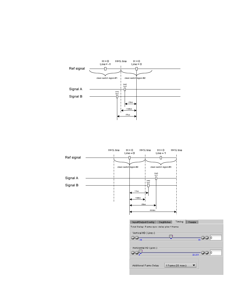
Practical examples:
Example 1: we have two 1080i59 sources, one that indicates an offset of -10
μs with respect to the reference (A)
and the other an offset of -25
μs (B). We know that a clean switch region limit is present at -½ line, which
corresponds to -14.8
μs. We can now determine that this switch will not be clean, because the two sources are on
opposite sides of the limit, and are therefore not in the same clean switch region.
Example 2: We have two 1080i59 sources, one that indicates an offset of 25
μs with respect to the reference (A)
and the other an offset of 17
μs (B). We know that a clean switch region limit is present at + ½ line and another one
at ½ line plus one line. These correspond to 14.8
μs and 44.4μs. We can now determine that this switch will be
clean, because the two sources are inside the same clean switch region.
Timing tab
The Timing tab provides access to timing adjustments
which affect the signal outputs. There are two slider
controls, each with a data reporting box which shows the
current value, and into which values can be typed directly.
The total delay is reported at the top of the window.
Vertical (lines): With this adjustment, a value ranging from
–16 to +15 lines compared to the reference or the
processing delay, may be set. This adjustment can be
used in conjunction with the horizontal timing adjustment.
Figure 3.6 Input/Output - Timing tab