Annex 2 – installing the optical interface – Grass Valley 3DX-3901 User Manual
Page 37
GUIDE TO INSTALLATION AND OPERATION
3DX-3901 | 33
ANNEX 2 – Installing the Optical Interface
Installing and removing the Fiber I/O interface cartridge requires special care. This annex describes the process.
Some rear panels used with the 3DX-3901 incorporate a fiber optic interface. The interface consists of two parts:
• A socket on the rear panel into which an SFP interface module is plugged
• An SFP (Small Form-factor Pluggable) module into which the optical fibers are plugged, and which
incorporates the optical/electrical interface
Cautions and Warnings
SFP Transmitter modules contain a class 1 laser, which emits invisible radiation whenever the module is
powered up. Because the SFP is hot-swappable, the module may be powered up as soon as it is installed.
DO NOT LOOK INTO AN OPERATING SFP MODULE’S CONNECTORS, AS EYE DAMAGE MAY RESULT.
The SFP module is sensitive to electrostatic discharge (ESD). It is recommended that you use an ESD-
preventive wrist strap grounded to the Densité chassis while handling the SFP module.
SFP modules are subject to wear, and their useful lifetime is reduced each time they are inserted or
removed. Do not remove them more often than is absolutely necessary.
Never remove or install an SFP module with the fiber optic cables connected. Damage to the cables could
result.
The presence of dust and debris can seriously degrade the performance of an optical interface. It is
recommended that you insert a dust plug into the SFP module whenever a fiber optic cable is not
connected.
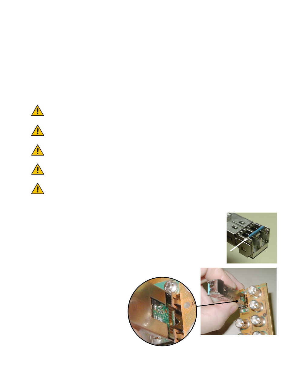
Installing an SFP module
1. Make sure that the bale clasp lever is in the closed position
2. Position the SFP module so that the recessed slot is lined up with the
tab side of the socket.