Grass Valley 3DX-3901 User Manual
Page 8
GUIDE TO INSTALLATION AND OPERATION
4 | 3DX-3901
Note that in the case of HD signals of the same frame rate, any reference signal may be used to genlock any output
signal, regardless of scan type (progressive or interlaced). When a 720p/tri-level sync reference signal is used with
an interlaced output, the output is synchronized but there may be a delay of one field depending on when the
synchronization started.
3G/HD/SD IN – Serial digital input (note: SD is future use for this connector)
Connect up to two serial digital video signals, conforming to the SMPTE 292M standard for HD input signals, to the
BNCs labeled 3G/HD/SD IN 1 and 2. The 3DX-3901 will automatically switch to the detected line/frame rate format.
3G/HD/SD OUT A and B – Serial digital video outputs (note: SD is future use for this connector)
The 3DX-3901 provides two pairs of 3G/HD/SD SDI video outputs on BNC connectors, labeled 3G/HD/SD SDI
OUT A1 & A2, and 3G/HD/SD SDI OUT B1 & B2. The SDI video signal conforms to the SMPTE 424M, SMPTE
292M or SMPTE 259M-C standard.
3G/HD OUT C – Serial Digital Auxiliary Output
The 3DX-3901 provides a third 3G/HD SDI video output, labeled 3G/HD SDI OUT C. The SDI video signal
conforms to the SMPTE 424M or SMPTE 292M standard.
In addition to Side by Side and Over/Under encoding, this auxiliary output provides a means of monitoring 3D
characteristics with Anaglyph and Disparity signals. Refer to Figure 3.4 for a complete list of all possible
configurations.
AES IN / OUT – (future use)
Fiber I/O – Fiber-optic inputs and outputs
Rear panels whose part number ends in –F incorporate a fiber optic interface. The interface consists of two parts:
• A socket on the rear panel into which an SFP interface module is plugged
• An SFP (Small Form-factor Pluggable) module into which the optical fibers are plugged, and which
incorporates the optical/electrical interface
The optical fibers must be terminated in an LC connector.
See Annex 2 for instructions on installing and removing the SFP interface module, and for plugging and unplugging
the LC-terminated fibers.
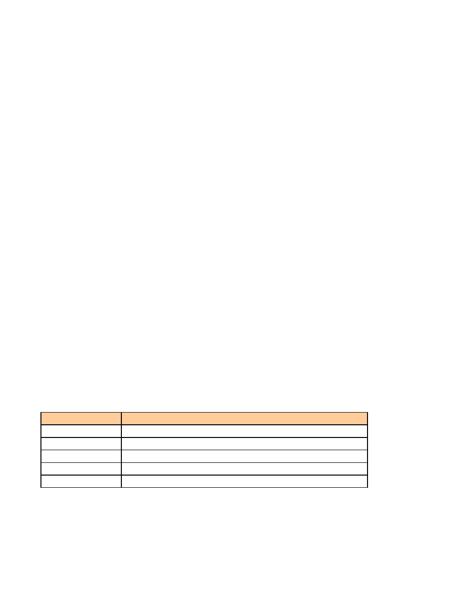
The current SFP modules supported are:
SFP Modules
Description
SFP-RR-LC
Dual Rx module with LC connector
SFP-TT-S13S13-LC
Dual Tx module at 1310 nm with LC connector
SFP-RT-S13-LC
Single Rx and Tx transceiver module at 1310 nm with LC connector
SFP-R-LC
Single Rx module with LC connector
SFP-T-S13-LC
Single Tx module at 1310 nm with LC connector