2 connector locations side panels, Connector locations side panels, Script light connector power input connector – Grass Valley LDK 4410 User Manual
Page 74
Advertising
74
LDK 4410 + LDK 5420 3G Fiber Transmission System User’s Guide (v1.0)
Chapter 6 - Connectors
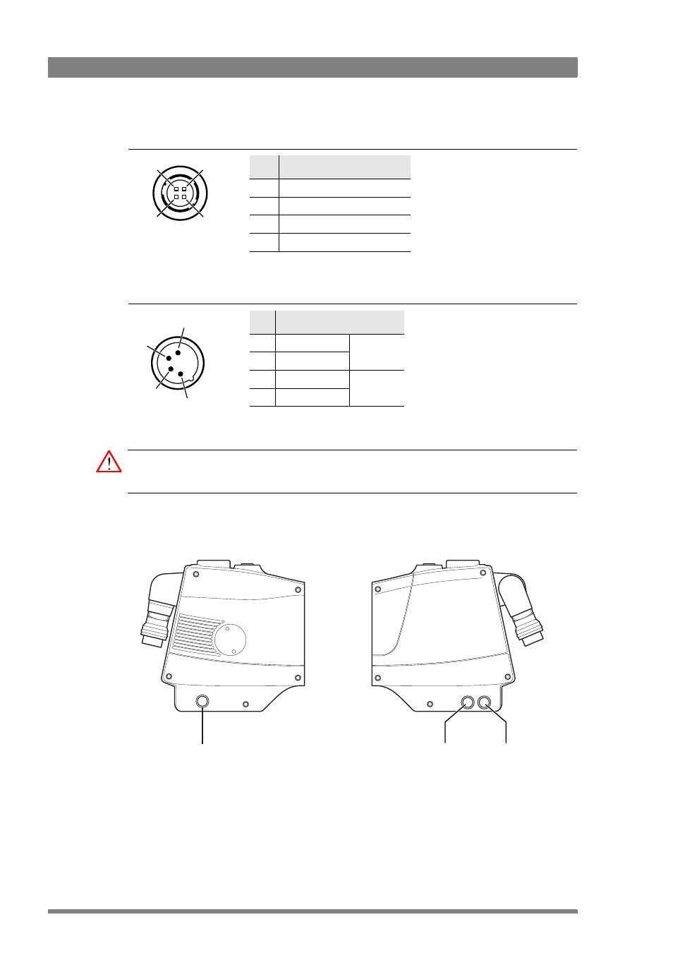
Script light connector
Power input connector
Caution
The input voltage must not exceed 17 V.
6.2.2 Connector locations side panels
Pin
Description
1
GND
2
Not connected
3
Not connected
4
12 V
Hirose 4-pin female
3
2
4
1
Shield of cable directly to the
connector housing.
Manufacturer code: HR10A-7R-6S
3
2
4
1
This socket accepts a DC voltage of
15 V nominal.
XLR 4-pin male
Pin Description
1
GND
Pins 1 & 2
are bridged
2
GND
3
11.5 to 17 V
Pins 3 & 4
are bridged
4
11.5 to 17 V
TP
AUX
TRACK
Reference in / Teleprompter
out connector
Auxiliary
connector
Tracker
connector
Advertising