Connecting analog composite video out, Connecting analog composite video out -13, Analog composite out cable connections -13 – Grass Valley PDR 200 Installation User Manual
Page 43
Connecting Video
Profile Video File Server Installation
2-13
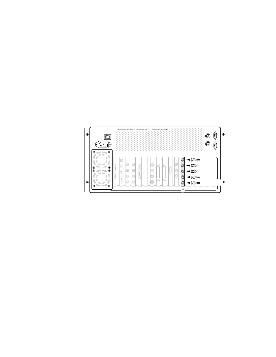
Connecting Analog Composite Video Out
The Profile Video File Server may include an Analog Composite Video Out board
which provides up to four channels of analog composite video output. The board also
has a Monitor D connector which is the Out D video with time code burn-in available.
Figure 2-13 shows analog composite video out cable connections for a typical
location, slot J6. Refer to the rear panel labels or Tables 1-2 through 1-6 in Chapter 1,
pages 1-9 through 1-13, to determine the slot location of this board in your system.
1. Place an EMI gasket on each BNC connector as shown in Figure 2-6, page 2-7.
2. Attach four BNC cables for composite video outputs to the OUT A, OUT B,
OUT C, and OUT D connectors.
3. Attach a BNC cable for the Out D output with time code burned-in to the
Monitor D connector (optional)
Figure 2-13. Analog Composite Out Cable Connections
J1
J17
J13
J16 J15 J14
J6
J7
J4 J3 J2
J5
J12 J11
J9 J8
J10
9676-21
Video Out
Analog Composite
Out B
Out A
Out C
Out D
Monitor D