Ethernet connector, Appendix b – Grass Valley PDR 200 Installation User Manual
Page 98
Advertising
Appendix B
B-2
Profile Video File Server Installation
Ethernet Connector
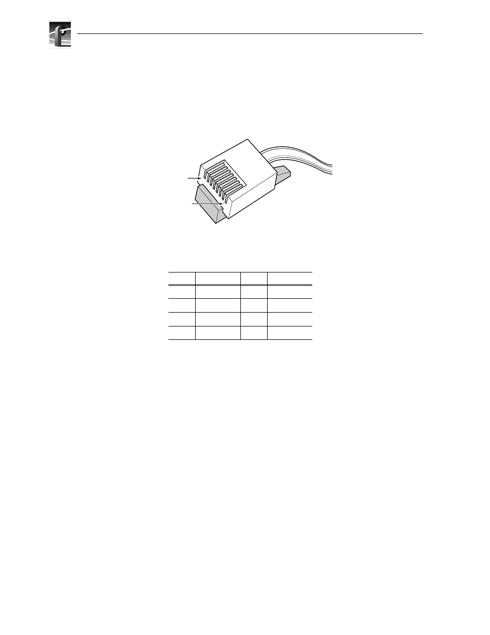
The Ethernet connector located on the System CPU board in slot J1 is an 8-pin RJ-45
snap-in telephone-type connector which supports Category 5 unshielded twisted pair
cable. Figure B-2 shows the RJ-45 connector and Table B-2 lists the pin-outs.
Figure B-2. Ethernet RJ-45 Connector
Table B-2. RJ-45 Connector Pin-outs
Pin #
Signal
Pin #
Signal
1
Transmit +
5
not used
2
Transmit -
6
Receive -
3
Receive +
7
not used
4
not used
8
not used
9676-18
Pin 8
Pin 1
8
7
6
5
4
3
2
1
Advertising
This manual is related to the following products: