HEIDENHAIN TNC 620 (340 56x-01) User Manual
Page 142
142
5.4 Thr
ee-Dimensional T
ool Compensation (Sof
tw
ar
e Option
2)
Example: Block format with surface-normal vectors and tool
orientation
The feed rate F and miscellaneous function M can be entered and
changed in the Programming and Editing mode of operation.
The coordinates of the straight-line end point and the components of
the surface-normal vectors are to be defined by the CAM system.
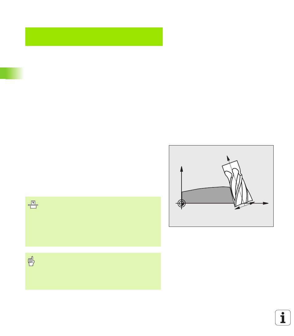
Peripheral milling: 3-D radius compensation
with workpiece orientation
The TNC displaces the tool perpendicular to the direction of
movement and perpendicular to the tool direction by the sum of the
delta values DR (tool table and TOOL CALL). Determine the
compensation direction with radius compensation RL/RR (see figure,
traverse direction Y+). For the TNC to be able to reach the set tool
orientation, you need to activate the function M128 (see “Position der
Werkzeugspitze beim Positionieren von Schwenkachsen beibehalten
(TCPM): M128 (Software-Option 2)” on page 308). The TNC then
positions the rotary axes automatically so that the tool can reach the
defined orientation with the active compensation.
LN X+31.737 Y+21.954 Z+33.165
NX+0.2637581 NY+0.0078922 NZ0.8764339
TX+0.0078922 TY–0.8764339 TZ+0.2590319 F1000 M128
LN:
Straight line with 3-D compensation
X, Y, Z:
Compensated coordinates of the straight-line end point
NX, NY, NZ:
Components of the surface-normal vector
TX, TY, TZ:
Components of the normalized vector for workpiece
orientation
F:
Feed rate
M:
Miscellaneous function
X
Z
RL
RR
This function is possible only on machines for which you
can define spatial angles for the tilting axis configuration.
Refer to your machine manual.
The TNC is not able to automatically position the rotary
axes on all machines. Refer to your machine manual.
Note that the TNC makes a compensating movement by
the defined delta values. The tool radius R defined in the
tool table has no effect on the compensation.
Danger of collision!
On machines whose rotary axes only allow limited
traverse, sometimes automatic positioning can require
the table to be rotated by 180°. In this case, make sure
that the tool head does not collide with the workpiece or
the clamps.