4 option components, Profibus-dp si-p3 option, Communication connector – Yaskawa 1000 Series Drive Option - Profibus-DP Installation User Manual
Page 10: Nameplate (refer to, Figure 1, 4option components
10
YASKAWA ELECTRIC TOBP C730600 42C 1000-Series Option SI-P3 Installation Manual
4 Option Components
4
Option Components
◆
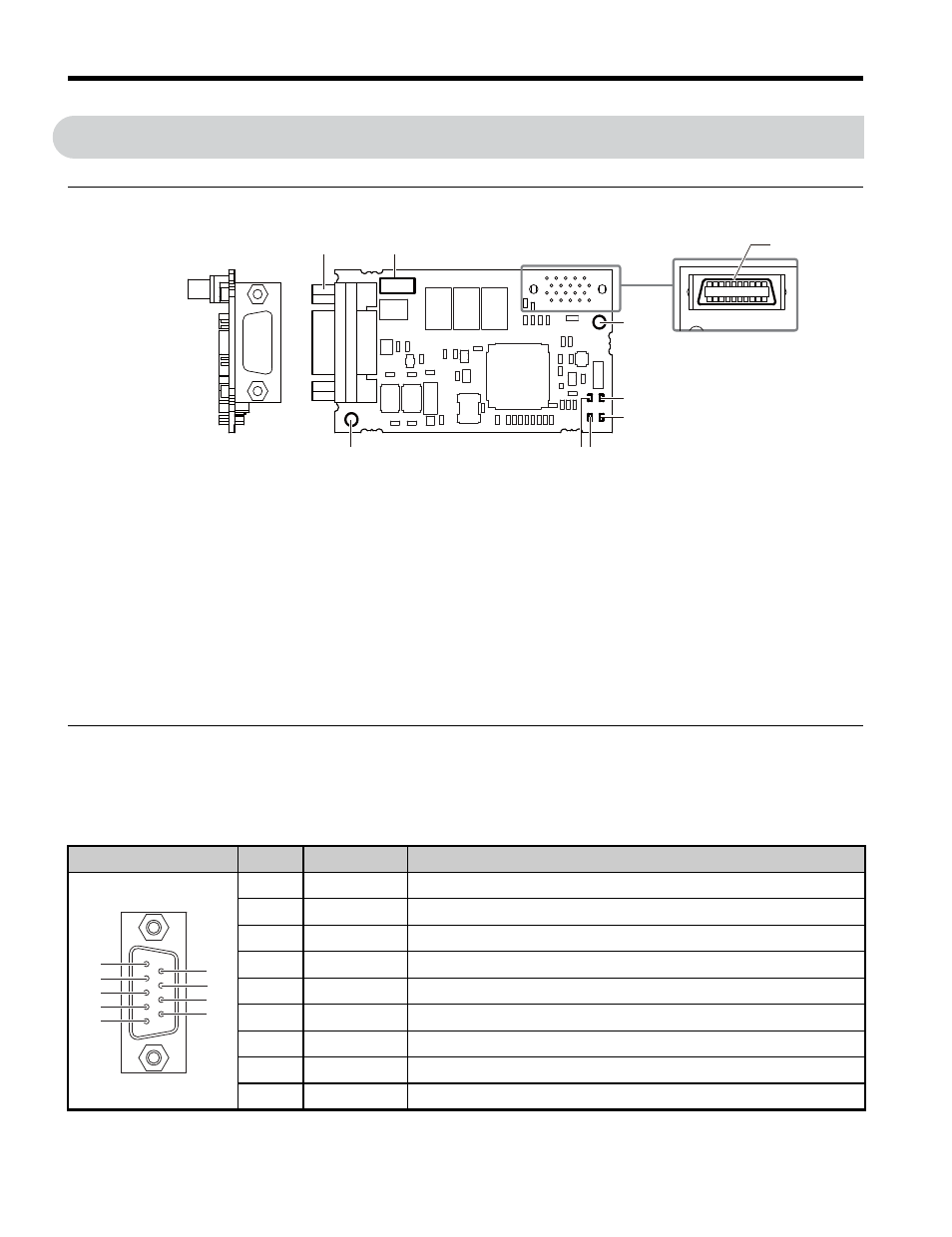
PROFIBUS-DP SI-P3 Option
Figure 1
Figure 1 PROFIBUS-DP Option Components
◆
Communication Connector
The option has a 9-pin D-sub connector to connect to a PROFIBUS network.
Table 3 Communication Connector (9-pin D-sub)
A – Communication
connector
F – LED (COMM)
B – Model number
G – LED (BF)
C – Connector (CN5)
H – LED (ERR)
D – Installation hole
I – Ground terminal and installation hole
<1>
Refer to Option LED Display on page 11
for details on the LEDs.
<2> The ground wire provided in the option shipping package must be connected during installation.
E – LED (RUN)
Connector
Pin
Signal
Description
1
Shield
Connected to the metal-shell (no direct FG-connection)
2
–
–
3
RxD/TxD-P
Receive/Transmit data; line B (red)
4
CNTR-P
Control signal for repeaters (direction control)
5
DGND
Data ground (reference voltage to VP)
6
VP
Power supply output for bus termination (for termination resistor)
7
–
–
8
RxD/TxD-N
Receive/Transmit data; line A (green)
9
–
–
C
A
B
D
E
F
H G
I
SI-P3
Communication connector bottom view
Underside
1
5
6
9
7
8
2
3
4