5 installation procedure – Yaskawa EtherNet/IP User Manual
Page 19
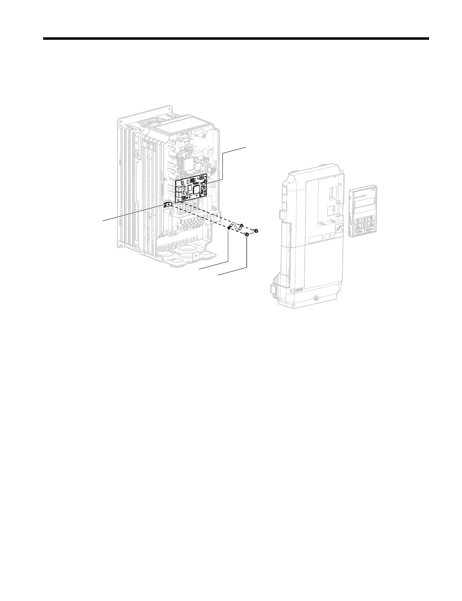
4.
Connect the ground wire (I) to the ground terminal (K) using one of the remaining
provided screws (H). Connect the other end of the ground wire (I) to the remaining
ground terminal and installation hole on the option (B) using the last remaining
provided screw (H) and tighten both screws to 0.5 to 0.6 N
•m (4.4 to 5.3 in lbs).
NS MS
F
G
M
H
TX RX
Figure 6 Connect the Ground Wire
Note:
There are two screw holes on the drive for use as ground terminals. When connecting three
options, two ground wires will need to share the same drive ground terminal.
5.
Route the option wiring.
Depending on the drive model, some drives may require routing the wiring through
the side of the front cover to the outside to provide adequate space for the wiring.
Refer to the Peripheral Devices & Options section of the drive Quick Start Guide or
Technical Manual for more information on wire routing of specific models.
Route the wiring through the side of the front cover to the outside. In these cases,
using diagonal cutting pliers, cut out the perforated openings on the left side of the
drive front cover as shown in
-A. Use a file or sandpaper to make the sharp
edges along the cutout smoother to prevent any damage to the wires. Route the wiring
inside the enclosure as shown in
-B for drives that do not require routing
through the front cover.
Note:
Separate communication cables from main circuit wiring and other electrical lines.
5 Installation Procedure
YASKAWA TOEP YAICOM 16A 1000-Series Option Dual-Port EtherNet/IP SI-EN3D Installation Manual
19