5 installation procedure – Yaskawa PG-E3 Motor Encoder Feedback User Manual
Page 15
5 Installation Procedure
14
YASKAWA ELECTRIC TOBP C730600 52C 1000-Series Option PG-E3 Installation Manual
4.
.
Refer to Wire Gauges and Tightening
to confirm that the proper tightening torque is applied to each
terminal. Take particular precaution to ensure that each wire is properly connected
and wire insulation is not accidentally pinched into electrical terminals.
WARNING! Fire Hazard. Tighten terminal screws to the specified tightening torque. Loose electrical
connections could result in death or serious injury by fire due to overheating. Tightening screws beyond the
specified tightening torque may cause erroneous operation, damage the terminal block, or cause a fire.
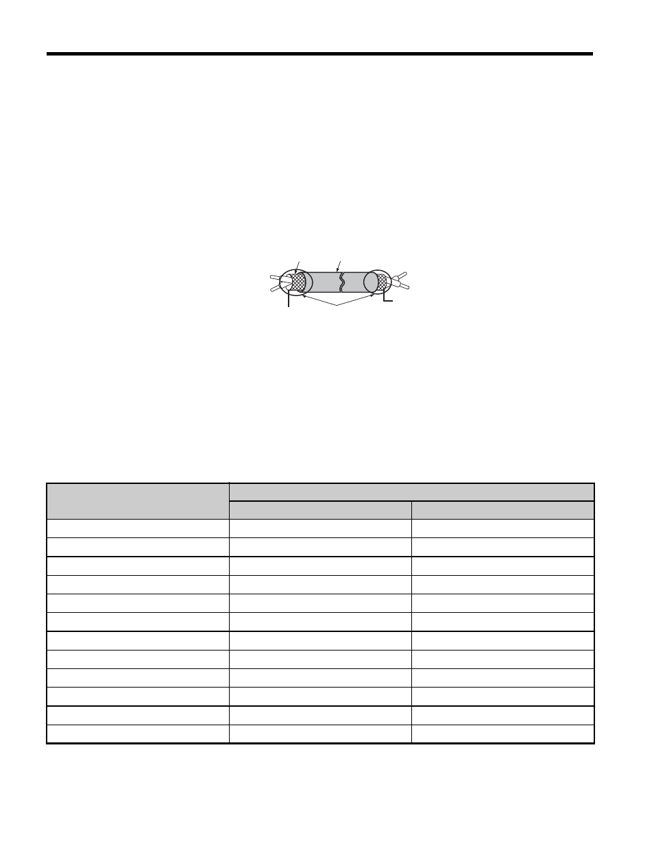
NOTICE: Heat shrink tubing or electrical tape may be required to ensure that cable shielding does not
contact other wiring. Insufficient insulation may cause a short circuit that can damage the option or drive.
Figure 6
Figure 6 Preparing Ends of Shielded Cable
5.
Wire the motor PG encoder to the terminal block on the option using a
HEIDENHAIN 17-pin cable. Refer to
for wiring instructions.
Limit the length of all motor output power cables to less than 10 m.
Refer to Option Terminal Functions on page 19
for a detailed description of the
option board terminal functions.
Table 2
PG Encoder Cable Specification
Option Terminal
PG Encoder Cable
Color
PG Encoder Side
IP
Brown/Green
Up
IG
White/Green
0V
A+
Green/Black
A+
A–
Yellow/Black
A–
B+
Blue/Black
B+
B–
Red/Black
B–
C+
Gray
C+
C–
Pink
C–
D+
Yellow
D+
D–
Purple
D–
R+
Red
R+
R–
Black
R–
Insulation
Shield sheath
Shield
PG option terminal
PG at motor
FE/SD
Ground Terminal
(Insulate with electrical tape
or shrink tubing)
E3