Installation – Yaskawa VS-616G5 InterBus-S Control Card SI-R User Manual
Page 4
Page 4
VS-616G5 Option Instruction Manual: InterBus-S Control Card SI-R
INSTALLATION
1.
Before attempting to install or use the InterBus-S Control Card SI-R, please read these instruc-
tions.
2.
After unpacking the card, verify that the code number is correct and that no damage has
occurred during shipping. Contact your YASKAWA representative if you require any assis-
tance.
3.
Turn OFF the main electrical power to the inverter.
4.
Remove the inverter’s digital operator. Then remove the inverter’s front cover. Refer to the VS-
616G5 User’s Manual for specific removal instructions for your particular inverter size.
5.
Verify that the indicator CHARGE lamp is OFF (power OFF indication).
6.
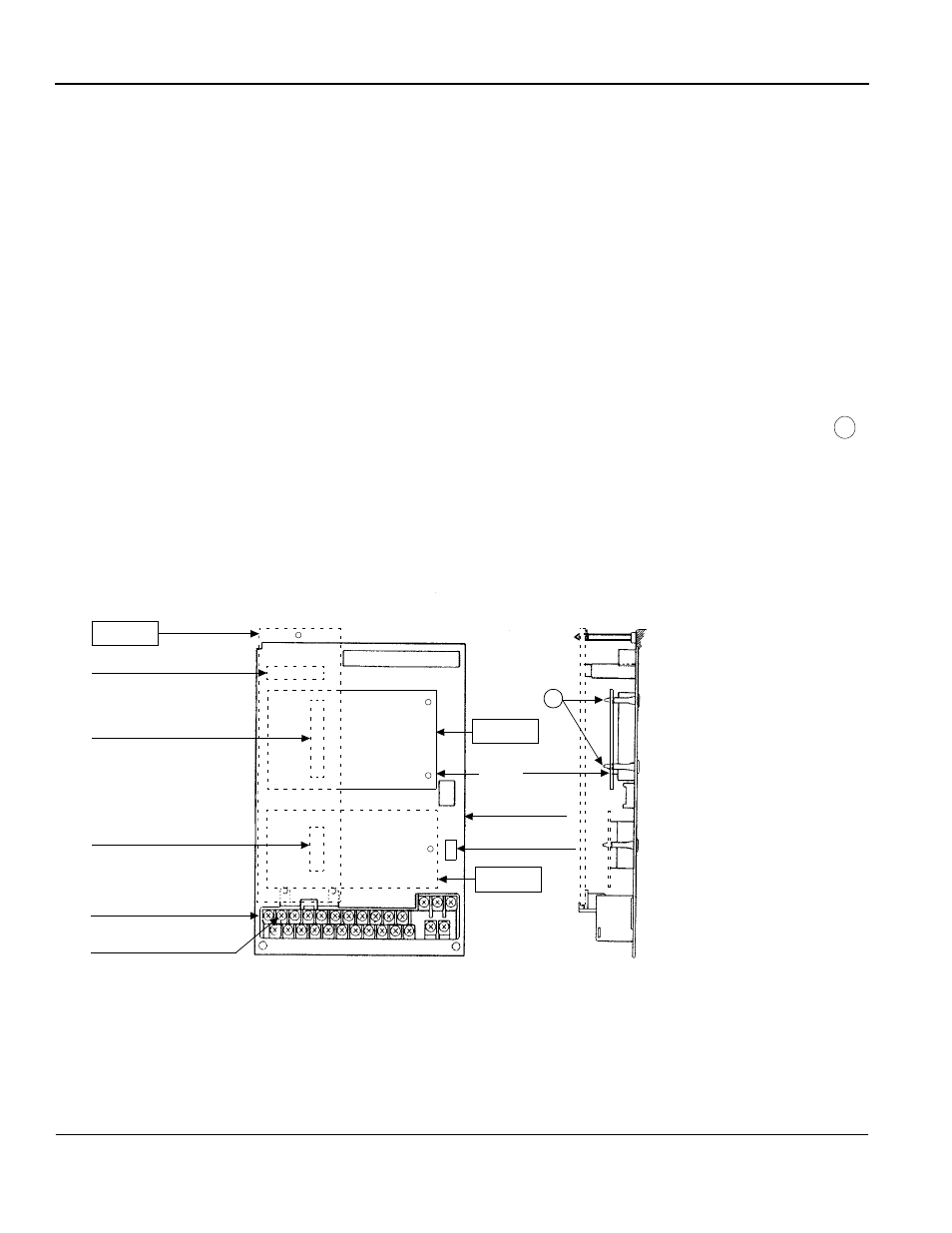
Plug the 2CN connector of the InterBus-S Control Card SI-R into the 2CN connector (60 pins)
on the control board of the inverter as illustrated in Fig. 2 below. Gently push the SI-R card until
the stand-off posts engage the two holes on the option card. Secure the SI-R card. (See part
of the side view below).
7.
Attach the green grounding load wire (PE-Protected Earth) cable to terminal 12 of the VS-
616G5 control board.
8.
Replace the inverter cover. Refer to Figs. 3 and 4 for correct wiring of the InterBus-S Control
Card and the Control Board. Note: The cable colors indicated meet the InterBus-S standard.
A
Option A
7CN
Top
Option C
Option D
Control board
Bottom
Front View
Grounding terminal 12
Connector
3CN Option D connector
2CN Option C connector
4CN Option A connector
terminal
Mounting base
A
Side View
Fig. 2 Installation of the InterBus-S Control Card SI-R
SI-R
of inverter
6CN connector