Wiring, Fig. 4 wiring of the interbus-s control card si-r, Fig. 5 installation of the rbst signal – Yaskawa VS-616G5 InterBus-S Control Card SI-R User Manual
Page 6
Page 6
VS-616G5 Option Instruction Manual: InterBus-S Control Card SI-R
WIRING
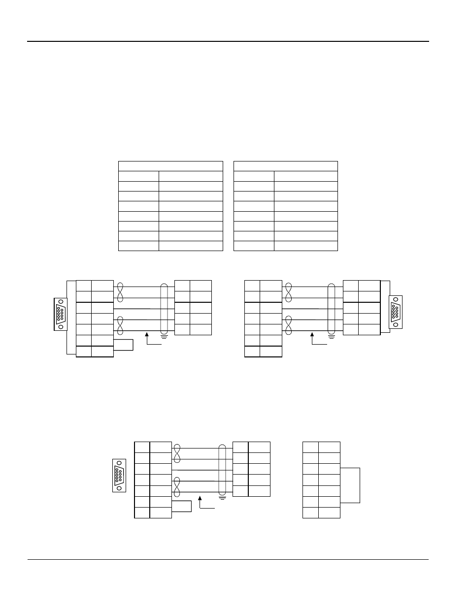
InterBus-S Terminal Blocks
The InterBus-S network cables are connected to the option board on the left side of the module,
using the two terminal blocks (Phoenix contact MKDS1-6 and MKDS1-7). There is one terminal
block (JP1) for the remote bus IN (i.e., from the previous InterBus-S unit), and one terminal block
(JP2) for the remote bus OUT (i.e., to the next InterBus-S unit). The pin layout of the connectors
follows the InterBus-S standard. (Refer to Table 3 below.)
Note: If the InterBus-S option card is the last unit on the bus, the RBST signal must be connected to
GND as illustrated below.
Table 3: InterBus-S Pin Layout
Bus IN (JP1)
Bus OUT (JP2)
Pin
Function
Pin
Function
1
DO1
1
DO2
2
/DO1
2
/DO2
3
DI1
3
DI2
4
/DI1
4
/DI2
5
GND BUS
5
GND
6
SHIELD
6
RBST
—
—
7
PE
Fig. 4 Wiring of the InterBus-S Control Card SI-R
DO
DO
/DO
GND
DI
/DI
/DO
GND
DI
/DI
1
2
5
3
4
1
6
3
2
7
5
9
Yellow
Green
Brown
Grey
Pink
BUS IN (JP1)
From previous unit
Male
DO
DO
/DO
GND
DI
/DI
RBST
PE
/DO
GND
DI
/DI
1
6
3
2
7
1
2
5
3
4
6
7
Yellow
Green
Brown
Grey
Pink
To next unit
BUS OUT (JP2)
Female
DB9
Connector
DB9
Connector
*
*
Fig. 5 Installation of the RBST signal
* Standard color coding of InterBus-S communications cable
DO
DO
/DO
GND
DI
/DI
/DO
GND
DI
/DI
1
2
5
3
4
1
6
3
2
7
5
9
Yellow
Green
Brown
Grey
Pink
BUS IN (JP1)
From previous unit
Male
DO
/DO
GND
DI
/DI
RBST
1
2
5
3
4
6
7
BUS OUT (JP2)
PE
*