7 option card installation – Yaskawa L1000E AC Drive CIMR-LEA User Manual
Page 157
7 Option Card Installation
YASKAWA TOEPYAIL1E01A YASKAWA AC Drive L1000E Quick Start Guide
157
Op
tion
Ca
rd
In
st
al
lat
io
n
7
Crimp Terminals
Yaskawa recommends using CRIMPFOX 6 by Phoenix Contact or equivalent crimp terminals with the specifications
listed in
for wiring to ensure proper connections.
Note: Properly trim wire ends so loose wire ends do not extend from the crimp terminals.
Table 51 Crimp Terminal Sizes
6.
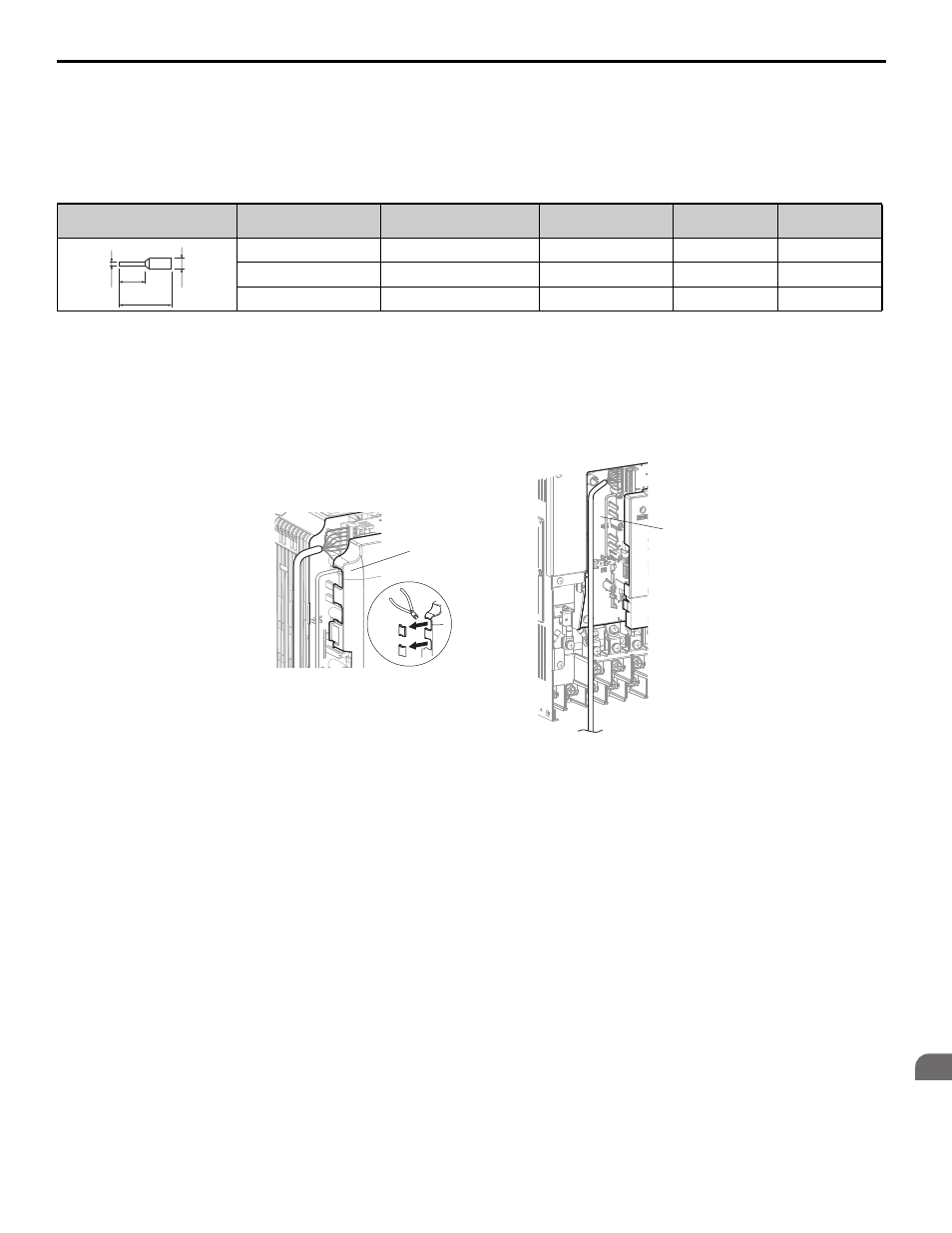
Route the option wiring.
Depending on the drive model, some drives may require routing the wiring through the side of the front cover to
the outside. For drive models CIMR-LE2A0018 through 2A0041, 4A0009 through 4A0023, cut out the perforated
openings on the left side of the drive front cover as shown in
-A and leave no sharp edges to damage
wiring.
Route the wiring inside the enclosure as shown in
-B for drive models CIMR-LE2A0047 through
2A0432, 4A0030 through 4A0260 that do not require routing through the front cover.
Figure 90
Figure 99 Wire Routing Examples
Wire Gauge
mm
2
Phoenix Contact Model
L
mm (in)
d1
mm (in)
d2
mm (in)
0.25 (24 AWG)
AI 0.25 - 6YE
10.5 (13/32)
0.8 (1/32)
2 (5/64)
0.34 (22 AWG)
AI 0.34 - 6TQ
10.5 (13/32)
0.8 (1/32)
2 (5/64)
0.5 (20 AWG)
AI 0.5 - 6WH
14 (9/16)
1.1 (3/64)
2.5 (3/32)
A – Route wires through the openings
provided on the left side of the
front cover.
(CIMR-LE2A0018 through 2A0041,
4A0009 through 4A0023)
<1> The drive will not meet NEMA Type 1 requirements if wiring is exposed outside the enclosure.
B – Use the open space provided
inside the drive to route option
wiring.
(CIMR-LE2A0059 through 2A0432,
4A0030 through 4A0260)
d1
d2
6 mm
(0.24 in.)
L
B
A