6 electrical installation – Yaskawa V1000 NEMA Type 4X/IP66 User Manual
Page 33
6 Electrical Installation
YASKAWA ELECTRIC TOBP C710606 35D YASKAWA AC Drive - V1000 NEMA Type 4X/IP66 Installation Manual
33
3.
Tighten the cable gland caps.
4.
Connect the wires to the main and control circuit terminals.
■
Reattaching the Front Cover
1.
Insert the LED operator cable into the correct port on the drive. Refer to the
2.
Replace the front cover on the drive and fasten the screws according to
.
NOTICE: Tighten all screws to the specified tightening torque. Loose screws may allow moisture or dust to
enter the protective enclosure and damage drive components.
NOTICE: Do not pinch or damage the sealing gasket when attaching the front cover. Damage to the gasket
may allow moisture or dust to enter the protective enclosure and damage drive components.
NOTICE: Do not use silicone sealant with cable glands or front cover to reinforce waterproofing. Corrosive
vapors produced by the sealant can damage circuit boards and compromise the watertight integrity of the
protective enclosure.
NOTICE: Do not pinch the LED operator cable between the waterproof/dustproof enclosure and the front
cover when putting the front cover back on. This could damage the operator cable.
■
Front Cover Screws and Tightening Torque
Refer
for tightening torque specifications.
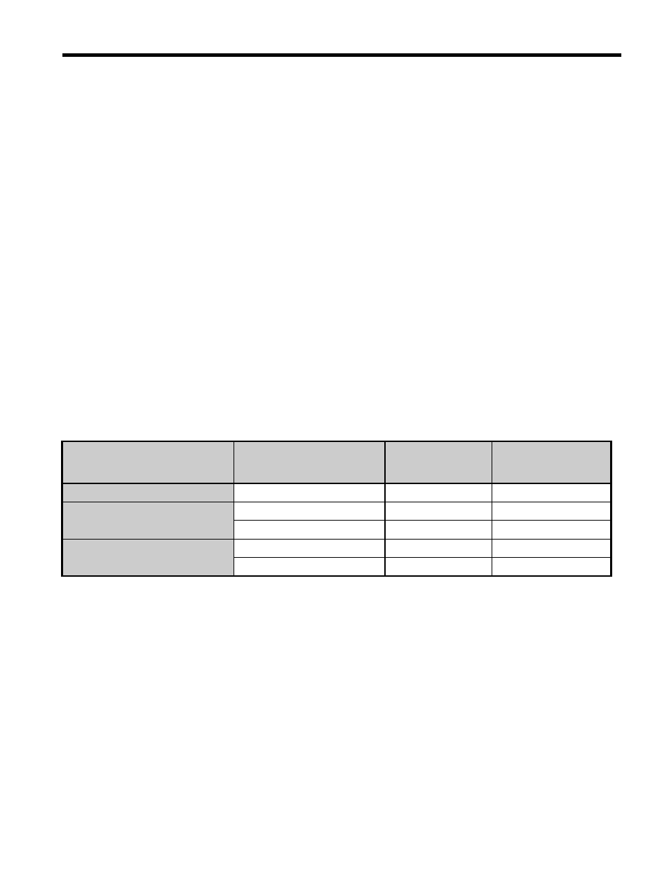
Table 16 Front Cover Installation Screws and Tightening Torque
Voltage Class
Model No. CIMR-V
Installation
Screw Size
Tightening Torque
Nm
(lb-in)
Single Phase 200 V Class
BA0001 to BA0012
M5
2.0 to 2.5 (17.7 to 22.1)
Three Phase 200 V Class
2A0001 to 2A0020
M5
2.0 to 2.5 (17.7 to 22.1)
2A0030 to 2A0069
M6
5.4 to 6.0 (47.8 to 53)
Three Phase 400 V Class
4A0001 to 4A0011
M5
2.0 to 2.5 (17.7 to 22.1)
4A0018 to 4A0038
M6
5.4 to 6.0 (47.8 to 53)