8 cable gland selection, Sc- series cable gland dimensions (asia) – Yaskawa V1000 NEMA Type 4X/IP66 User Manual
Page 41
8 Cable Gland Selection
YASKAWA ELECTRIC TOBP C710606 35D YASKAWA AC Drive - V1000 NEMA Type 4X/IP66 Installation Manual
41
■
SC/SCL Cable Glands for Control Circuit Wiring (Asia)
Table 22 Control Circuit Wiring Cable Glands
Refer to the Electrical Installation chapter of the drive Quick Start Guide for proper control
circuit wiring type, gauge, tightening torque and procedures
■
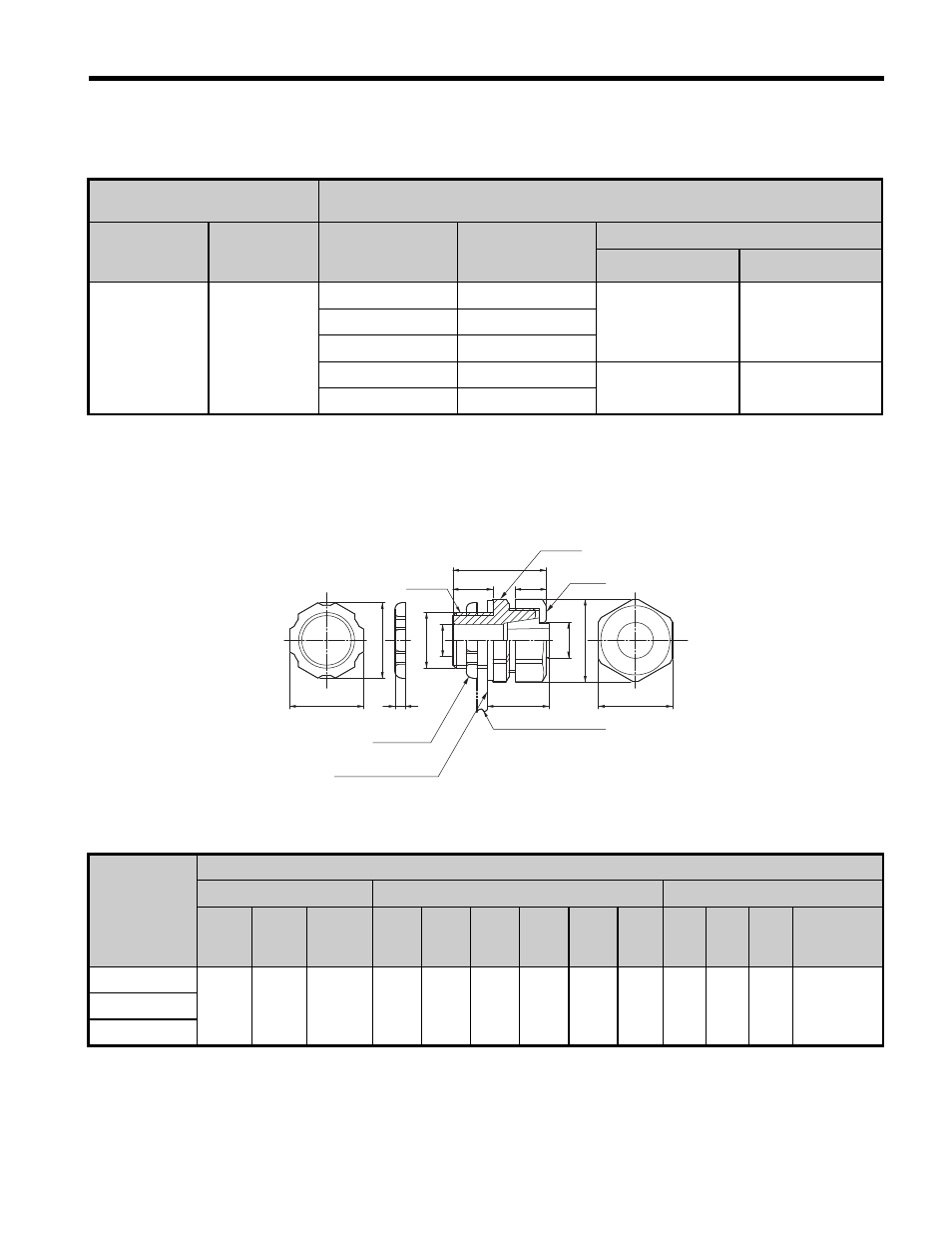
SC- Series Cable Gland Dimensions (Asia)
Figure 14
Figure 14 SC- Series Cable Gland (SC-)
Table 23 SC Series Cable Gland Dimensions
Drive-Side Conduit
Openings
Cable Gland (Seiwa)
Hole Diameter
(mm)
Number
of Holes
Appropriate
Wiring Diameter
(mm)
Product
Number
Tightening Torque Nm
Body, Cap
Body, Locknut
22
3
6.1 to 7.5
SC-3M
1 to 1.5
2 to 2.5
7.6 to 9.0
SC-3A
9.1 to 10.5
SC-3B
10.5 to 12.5
SCL-14A
2.5 to 2.9
2.9 to 3.4
12.5 to 14.5
SCL-14B
Model
Dimensions mm
Screw
Body, Cap
Locknut
Name Diam.
φJ
Length
K
A
B
C
φD
E
F
G
H
I
Rubber
Packing
Thickness
SC-3A
G 1/2
21.0
15
35
23
11.5
12
31.0 28.0 28.5
27
4
2.0
SC-3B
SC-3M
Screw
φ
J
φ
D1
φ
D
H
I
G
Max. A
K
C
Max. B
F
E
Installation plate
φD1 = φD
Locknut
Rubber packing
Body
Cap