Application 2712 - overview, 1 logical analog input (lai) summary, Gpd506/p5 – Yaskawa GPD506/P5 with Apogee FLN Option User Manual
Page 9
8
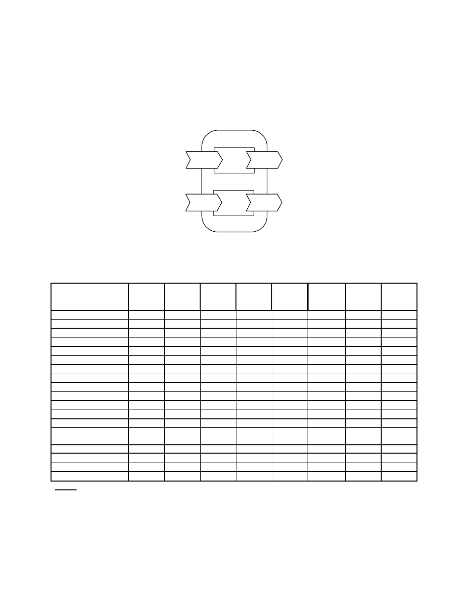
3. Application 2712 - Overview
The drive is configured, controlled, and monitored by a comprehensive set of Analog and Digital points,
as illustrated in Figure 6. Note the convention regarding inputs and outputs (i.e. Network Output = Drive
Input, Network Input = Drive Output).
This chapter summarizes the available points first by type and then by number. Additional detail can be
found in Section 4, Standard Operation, where points are grouped together by function.
Binary
Points
Analog
Points
GPD506/P5
Network
Outputs
Network
Outputs
Network
Inputs
Network
Inputs
Figure 6. Device Overview
3.1 Logical Analog Input (LAI) Summary
Point Description
Point #
GPD505
Monitor
GPD506/P
5
Monitor
Units
(SI)
Slope Intercept Min
Max
Network Address
1
n/a
n/a
1.0
0
1
255
Application Number
2
n/a
n/a
1.0
0
2712
2712
Output Frequency
3
U-02
U-02
Hz
0.1
0
0
Note 1
Output Percentage
4
U-02
U-02
%
0.1
0
0
100
Output Speed
5
U-02
U-02
rpm
1.0
0
0
Note 1
Output Current
6
U-03
U-03
A
0.1
0
0
Note 2
Output Power
8
n/a
U-06
kW
0.1
0
0
9999
Drive Temperature
9
n/a
Note 3
°C
1.0 0
Kilowatt Hour Meter
10
n/a
U-15
kWh
Note 5
0 0
9999
Megawatt Hour Meter
11
n/a
U-16
mWh
1.0
0
0
9999
DC Bus Voltage
13
U-05
U-05
V
1.0
0
0
Note 2
AC Output Voltage
14
U-04
U-04
V
1.0
0
0
Note 2
Elapsed Timer – Hrs
15
U-11
U-11
Hr
1.0
0
0
9999
Elapsed Timer – 10K Hrs
16
U-12
U-12
10K Hr
1.0
0
0
27
Fault Code
17
U-09
U-09
1.0
0
0
8191
Frequency Reference
61
U-01
U-01
Hz
0.1
0
0
Note 1
PID Feedback
62
n/a
U-13
Hz
0.1
0
0
Note 1
Read Parameter Data
71
Note 4
Note 4
Note 4
1.0 0
Note 4
Note 4
Notes
1. Value dependent on maximum output frequency of the drive. Default is 60.0 Hz.
2. Value dependent on drive capacity. Refer to appropriate Technical Manual.
3. Internal value only available via serial communication.
4. Value depends on the parameter being read (#70).
5. Slope is dependent on drive capacity. For drives with a rated current of 180 A or less, the slope is
0.1. For higher capacity drives, the slope is 1.0.