Connect the l, Option to the l, Communications network – Yaskawa LonWorks Option Card CM048 User Manual
Page 14: Set drive termination, Terminal s1 safety interlock control, Installation 1-8
Installation 1-8
Connect The L
ON
W
ORKS
Option To The L
ON
W
ORKS
Communications Network.
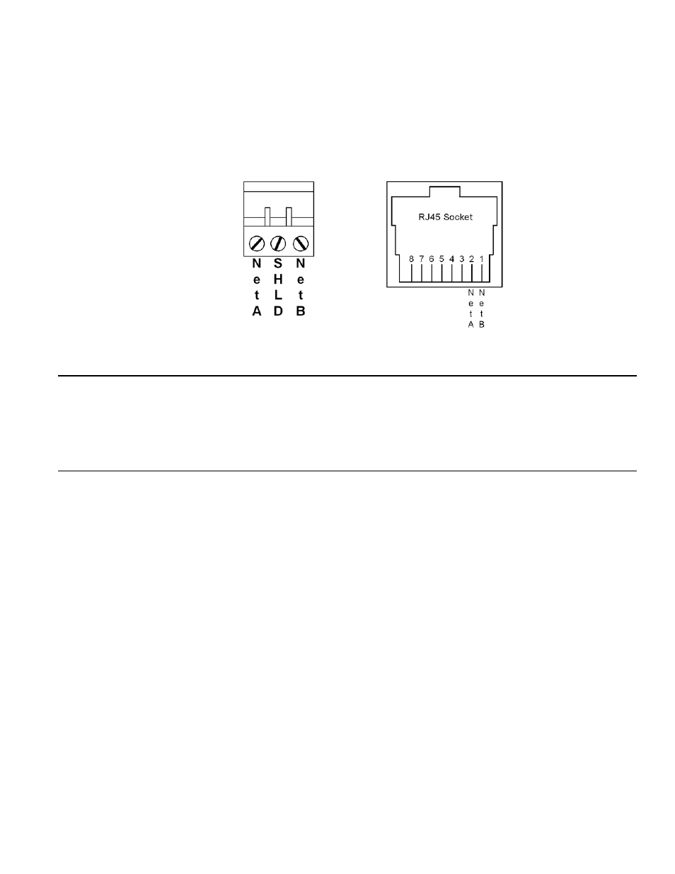
The LonWorks interface features Echelon’s Smart free topology transceiver (FT3150). The FT3150 transceiver is also directly compatible with
Echelon’s LPT-10 Link Power transceiver. A single twisted pair cable can be shared by these transceiver types. The primary network connection
is 3-way pluggable Phoenix-style connector included with the option card. The center position is for the shield while the outer positions are for
the twisted pair cable, as shown below. The network connection is polarity insensitive.
Connect the L
ON
W
ORKS
network cable to the 3-pin connector on the L
ON
W
ORKS
Option as shown below. The RJ45 connector is
typically used as a local network access point and is not recommended for network conection.
Tie the L
ON
W
ORKS
cable to a point near the connector to provide strain relief for the connector and cable connection.
Figure 1.6 – L
ON
W
ORKS
Option Connections
Set Drive Termination
Since the L
ON
W
ORKS
Option utilizes the RS485 connection to the drive, it is necessary to set the termination resistor to the ON position on each
drive’s terminal assembly. Refer to Figure 1.3 – L
ON
W
ORKS
Option E7, P7 and F7 Drive Connections, Figure 1.4 – L
ON
W
ORKS
Option E7L
Connections and, Figure 1.5 – L
ON
W
ORKS
Option G7 Drive Connections above for the location of the termination switch on the drive’s terminal
assembly.
Terminal S1 Safety Interlock Control
A normally closed safety interlock must be connected to the drive’s terminals S1 and SN. When the connection between S1 and SN is broken,
the drive will automatically stop. The drive Run will restart once the connection is re-established. Refer to the appropriate drive user,
programming and/or technical manual for the proper use and wiring of a safety interlock circuit. If a safety interlock is not used, a jumper must
be present between terminals S1 and SN.
For E7B and E7L units refer to the schematic and instructions that came with the unit, along with the appropriate technical manual for
connection and use of the safety interlock.