Gsm communication module, Power down the lightsys, Plug in the gsm module to the lightsys main board – RISCO Group LightSYS Ver 2.xx User Manual
Page 10
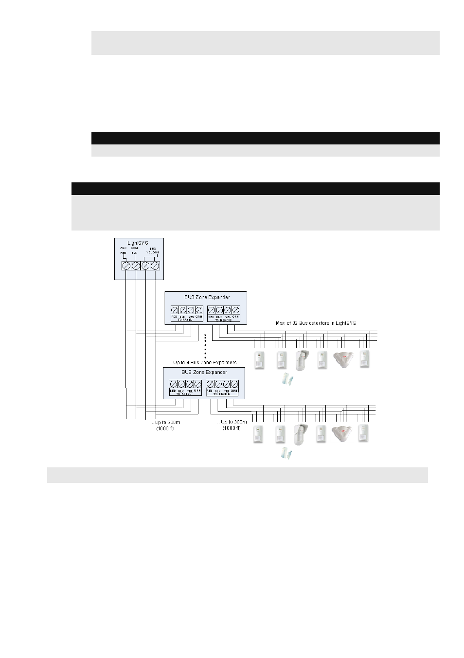
For maximum operation stability, it is best NOT to exceed a total 300 meters (1000 feet)
of wiring from the bus detector to the LightSYS panel.
Connecting Bus Detectors using a Bus Zone Expander (BZE):
1. Set the BZE ID number (1-3) using the DIP switches SW1 1-3.
2. Set the BZE SW2-3 to ON position.
3. Wire the BZE terminals marked as TO PANEL to the LightSYS Bus.
4. Set the bus detector ID number (1-32) using the detector's DIP switches.
Note:
Do not repeat the same ID twice on the same BZE.
5. Wire each detector's bus terminals to the relevant BZE's terminals marked as TO
DEVICE.(see figure below)
Note:
For maximum operation stability, it is best NOT to exceed a total of:
300 meters (1000 feet) of wiring from the BZE to the LightSYS panel.
300 meters (1000 feet) of wiring from the BZE to the last bus detector.
GSM Communication Module
The GSM Module provides voice and data communication on the LightSYS over the cellular
network
1. Power down the LightSYS.
2. Plug in the GSM module to the LightSYS main board.
3. Insert the dedicated SIM card and, if required, enter the enabling PIN code or disable the
SIM PIN Code in advance by placing it in a cell phone and disabling the code.
4. Attach the antenna plate and slide it into its right-wall housing. (See figure
, page 3)
5. Power up the LightSYS. The green LED should flash for thirty seconds, indicating the
network signal strength, and then steadily stay lit.
10
LightSYS Quick Installer Guide