Main unit dip switch settings, Connecting bus detectors, Connecting bus detectors to the main lightsys bus – RISCO Group LightSYS Ver 2.xx User Manual
Page 9
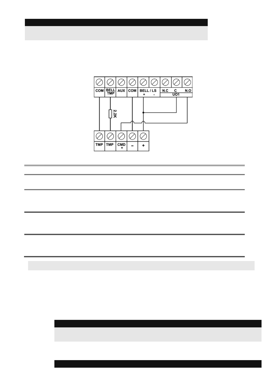
Important:
If you DO NOT use the terminal TMP BELL, remember to connect a 2.2KΩ
resistor (Resistor colors: Red, Red, Red) between TMP and COM.
6.
Wiring Utility Output 1 to Activate Self-Power Devices
Utility output 1 can be used to activate a self-powered siren or any other self-powered device.
7.
Main Unit DIP Switch settings
DIP Switch SW1
Status
1: Bell
ON: Bell: For bell or electronic siren with a built-in siren driver.
OFF (Default): For loudspeaker without a built-in sound driver.
2: Default
ON: Resets installer, sub-installer and grand master codes to their
default factory values and bypasses main unit front tamper alarm.
OFF (Default): Codes preserve their set values.
3: Extern - Back
Tamper Bypass
ON: Back tamper bypass is in effect. Use this setting during
programming and if no back tamper
has been connected to PLUG
2.
OFF (Default): No tamper bypass is in effect
4: Intern –
Front Tamper
Bypass
ON: Front tamper bypass is in effect. Use this setting when the
LightSYS is installed inside the metal enclosure RP432BM1.
OFF (Default): No tamper bypass is in effect
Connecting BUS Detectors
Up to 32 addressable bus detectors can be assigned to the LightSYS. Bus detectors can be wired to
the main bus or to a Bus Zone Expander (BZE).
For full installation instructions refer to the instructions supplied with each bus detector.
Connecting BUS Detectors to the Main LightSYS BUS:
1. Set the bus detector ID number (1-32) using the detector's DIP switches.
Note:
For WatchOUT, LuNAR, WatchIN, BWare and Seismic set the switch that defines the
detector operation mode to bus mode
.
2. Wire the bus terminals AUX(RED), COM (BLK), BUS (YEL) and BUS (GRN) to the
LightSYS Bus.
Note:
LightSYS Quick Installer Guide
9