Setting bus accessory id numbers – RISCO Group LightSYS Ver 2.xx User Manual
Page 6
Notes:
1. The parallel wiring system supports parallel connections from any point along the wiring.
2. The maximum wire run permitted is 300 meters (1000 feet) for all legs of the bus.
3. In case of bus communication problems, connect two 2.2KΩ resistors, one at each end of the data
bus terminals, between the green and yellow wires.
4. If connecting remote power supplies, do NOT connect the Red wire (+12v) between the Power
Supply Unit and LightSYS.
5. For long cable runs, please use the correct cable as stated in the Installation Manual, Wiring appendix.
1.
Setting Bus Accessory ID Numbers
For most devices, a DIP switch number must be set to identify its ID category number.
Devices are split into ‘Families’. Each ‘Family’ of devices has sequential identification numbers
which are set by the DIP switches. Before setting power on, define each module’s ID number by
setting the dipswitches as follows:
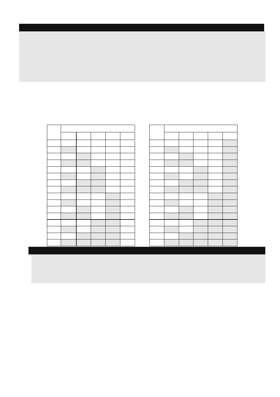
ID
DIP switches
ID
DIP switches
1
2
3
4
5
1
2
3
4
5
01
OFF OFF OFF OFF OFF
17
OFF OFF OFF OFF ON
02
ON
OFF OFF OFF OFF
18
ON OFF OFF OFF ON
03
OFF ON OFF OFF OFF
19
OFF ON OFF OFF ON
04
ON
ON OFF OFF OFF
20
ON ON OFF OFF ON
05
OFF OFF ON OFF OFF
21
OFF OFF ON OFF ON
06
ON
OFF ON OFF OFF
22
ON OFF ON OFF ON
07
OFF ON ON OFF OFF
23
OFF ON ON OFF ON
08
ON
ON ON OFF OFF
24
ON ON ON OFF ON
09
OFF OFF OFF ON OFF
25
OFF OFF OFF ON ON
10
ON
OFF OFF ON OFF
26
ON OFF OFF ON ON
11
OFF ON OFF ON OFF
27
OFF ON OFF ON ON
12
ON
ON OFF ON OFF
28
ON ON OFF ON ON
13
OFF OFF ON ON OFF
29
OFF OFF ON ON ON
14
ON
OFF ON ON OFF
30
ON OFF ON ON ON
15
OFF ON ON ON OFF
31
OFF ON ON ON ON
16
ON
ON ON ON OFF
32
ON ON ON ON ON
Notes:
•
Most accessories have four DIP switches, while bus detectors have five DIP switches
•
IDs 9–32 are only available for bus detectors.
•
If a DIP switch is changed on any device, it is necessary to shut down the device’s power and
then re-power it.
The first module in each category is defined as ID= 1.
Families that have sequential ID numbers are:
•
Keypads (LCD, LCD with proximity and wireless keypad (both 1- and 2-way)
•
Zone Expanders (8 zones expander, bus zone expander)
•
Outputs (4 relay output expander, 8 open collector output expander, 2 relay output expander
on 4A power supply, 2 relay output expander on Wireless zone expander, X-10 Outputs,
again, both 1-and 2-way)
•
Power Supplies (4A switching mode power supply)
•
Bus Zones
•
WL Zone Expanders
6
LightSYS Quick Installer Guide