Amprobe – Amprobe DMIII-Multitest Power-Quality-Recorder User Manual
Page 19
AMPROBE
DMIII MULTITEST
EN-17
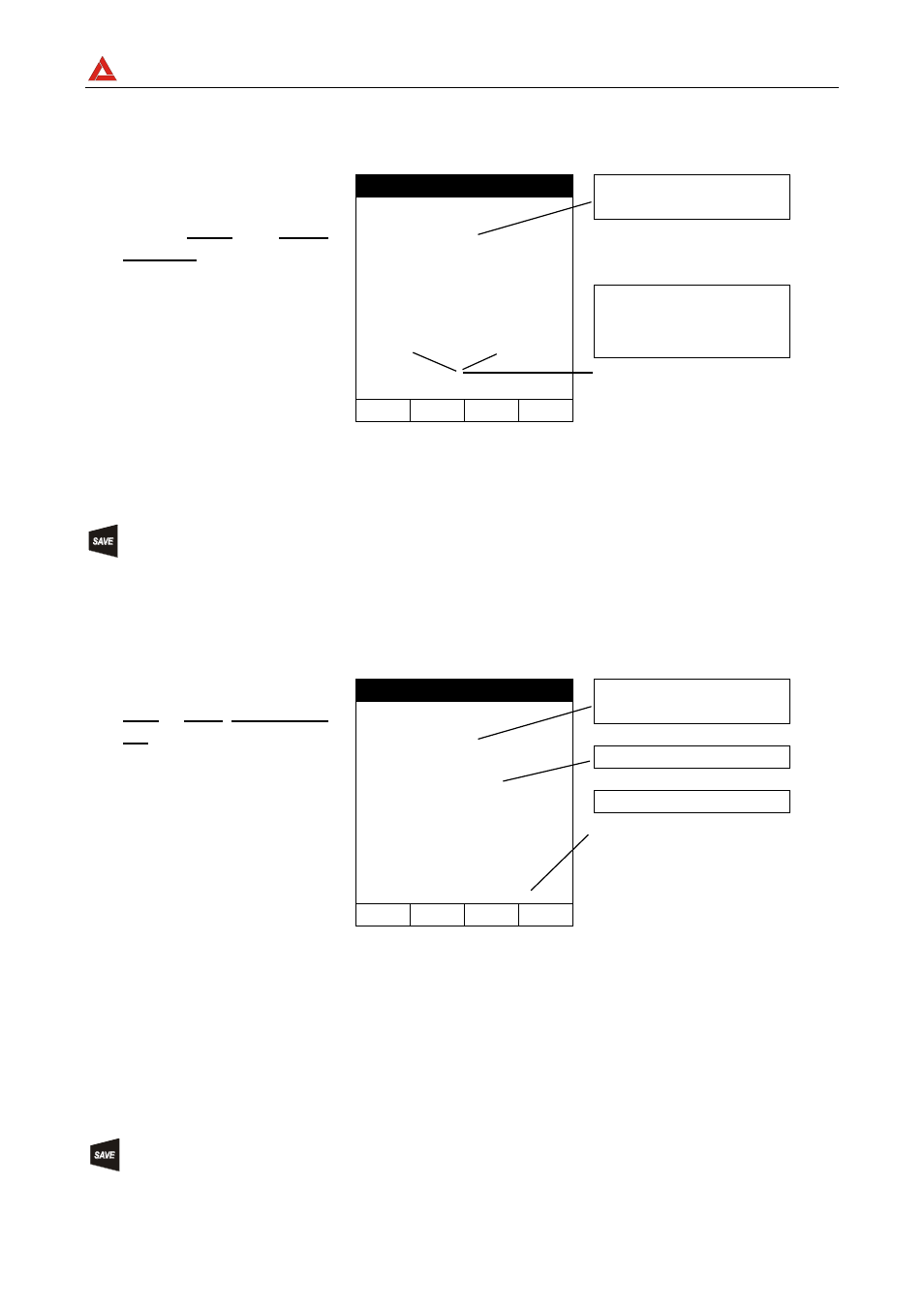
6.1.3. Results of "AUTO" mode
At the end of the test, if
the average resistance
value Ravg is lower
than 5
the instrument
emits a double sound
signal
indicating
the
positive outcome of
the test and displays a
screen similar to the
screen to the right.
LOW
05.06.01
Average resistance value
(Ravg)
1.05
R+ R-
1.07
1.03
219mA 219mA
AUTO 0.11
Resistance
values
and
corresponding test currents
obtained after exchanging
the polarities of test leads
FUNC CAL
The displayed result can be stored by pressing the SAVE key twice (refer to
paragraph 9.1).
6.1.4. Results of "RT+" and "RT-" modes
If a resistance value
RT+ or RT- lower than
5
is detected, the
instrument
emits
a
double sound signal
indicating the positive
outcome of the test
displays a screen similar
to the screen to the
right.
LOW
05.06.01
Max Resistance value of
R+ or R-.
1.07
219mA
RT+ 0.11
TIME: 10s
Test current
Duration of the Test
FUNC CAL
Note:
We recommend the use of alligator clips and to assure the alligator clips make good
contact with the conductor under test. Indeed, in this test the instrument gives as a
final result the maximum measured value of R+ or R- and using test leads instead of
alligator clips could give you faulty results due to faulty contact between the test leads
and conductor under test
The displayed result can be stored by pressing the SAVE key twice (refer to
paragraph 9.1).