Amprobe A-5000 Sheath Fault Locator User Manual
Page 10
8
Backtrack.
4.
Insert the A-5000 every 2’ (.5 m) until the arrow changes direction again.
5.
Move the A-5000 across the cable until a slight movement causes the arrow to change direction. The fault is located at the
6.
center of the A-5000.
Check entire cable for multiple faults. If more faults are present, check the “Active” LCD number at each fault site and
7.
compare it to the “Reference” number. The higher the “Active” number the larger the fault.
A-5000 RECEIvER tEChNICAL SPECIFICAtIoNS
Linear A-Frames For telecom Utilities:
Telecom faults, however, are typically higher resistance faults than power. The Linear A-frame A-5000 provides greater sensitivity
in the fault range of 100 KΩ – 10 MΩ to detect multiple faults in a cable.
A-Frame Receiver Controls And Indicators
See Figure 4-1 for the location of the Receiver controls described below:
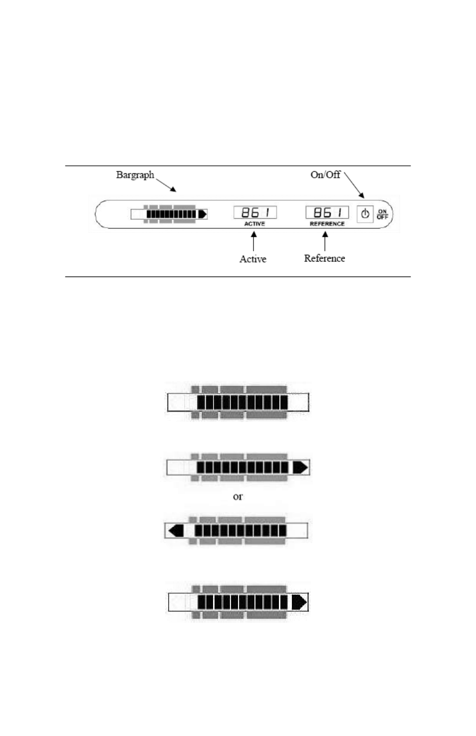
Figure 4-1: A-5000 Controls and Indicators
On/Off Button:
Push and release to turn ON. Push and release to turn OFF.
LCD Bar Graph Display:
The bar graph indicates three types of information:
Battery Status:
The solid bars indicate the battery level. If only one bar appears, replace the battery. The battery status is displayed for three
(3) seconds at Power ON.
Direction of Fault:
The flashing arrows will display the direction to the fault
Magnitude of Fault
The bar graph consists of twelve (12) bars with each bar representing the magnitude of the fault(s) as described below.