Amprobe A-5000 Sheath Fault Locator User Manual
Page 15
13
The A-Frame Receiver will repeat its battery test. After the battery test, the arrow facing the simulated fault (Red test clamp)
flashes and a potential gradient number is shown on the Active and Reference LCD display.
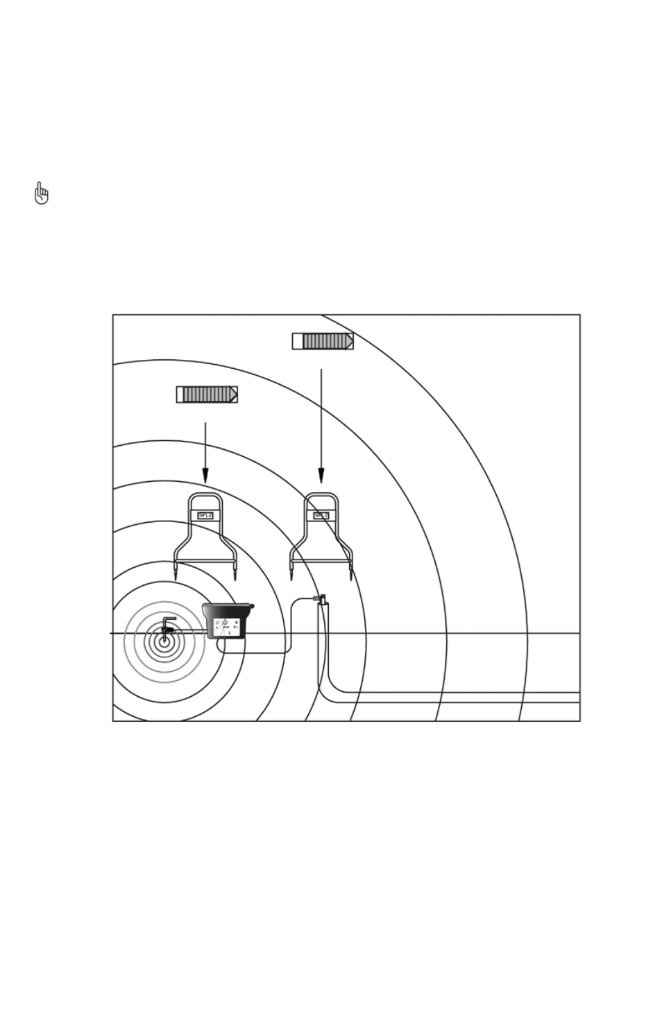
Rotate the A-5000 180°
7.
Note that the arrow now facing the red test clamp flashes. As the A-Frame is moved around the fault the arrow closest to the
simulated fault should flash.
oPERAtIoN
Synchronize the A-Frame Receiver
By synchronizing, the A-5000 memorizes the phase of the transmitter signal. This allows it to recognize the reverse phase signal
coming from the fault and direct you to it.
Resynchronize the Receiver every 45 minutes to maintain optimum calibration. You may do this near the ground rod or
near a fault. At the ground rod, the black A-Frame spike must be nearer to the ground rod with the white spike facing
toward the fault. At a fault, the white A-Frame spike must be nearer to the fault.
Hold the A-5000 so that the black spike is closest to the ground rod.
1.
Push the A-Frame spikes into the ground.
2.
Switch the A-5000 Receiver ON. Wait until the arrow flashes on the bar graph.
3.
If the arrow points away from the ground spike, there is a fault.
4.
If the arrow points towards the ground spike, there is no fault. Recheck the grounds and connections if a fault is wrongly
5.
given. See Figure 7-1.
Figure 7-1: Synchronizing the A-5000
Confirm that A Fault Exists
Remove the A-Frame from the ground.
1.
Rotate it 180° and re-insert it into the ground. The arrows should reverse directions and point away from the ground spike.
2.
trace the Cable With the R-5000 Receiver
The AT-5000 Utility Line Locator allows you to trace the line and search for the fault at the same time.
Check the R-5000 Receiver for cable tracing frequency. Aim the Receiver at the Red lead and cycle through the Receiver
1.
frequencies – 9.8 KHz or 82 KHz, to confirm that the selected tracing frequency is being received.
Trace and mark the cable as you proceed towards the fault.
2.
Pinpoint the Fault
Keep the A-5000 parallel to the target cable
1.
Insert the A-Frame every 10’ – 20’ (3 - 6 m). Follow the arrow and monitor the active number.
2.
When locating with the A-5000, make sure that the probes are inserted well into the ground. A good physical ground
3.
connection is needed to receive strong signal.