Amprobe A-5000 Sheath Fault Locator User Manual
Page 8
6
Plug Black and Red conductive leads into the transmitter.
2.
Stretch the Black-lead 180° away from conductor.
3.
Push the ground rod into earth and clamp the Black lead to ground rod. Establish the best ground possible. See Figure 3-1
4.
Figure 3-1: Clamping Black Lead to Ground Rod; Clamping Red Lead to Conductor
Clamp Red lead to target conductor sheath. See Figure 3-1
5.
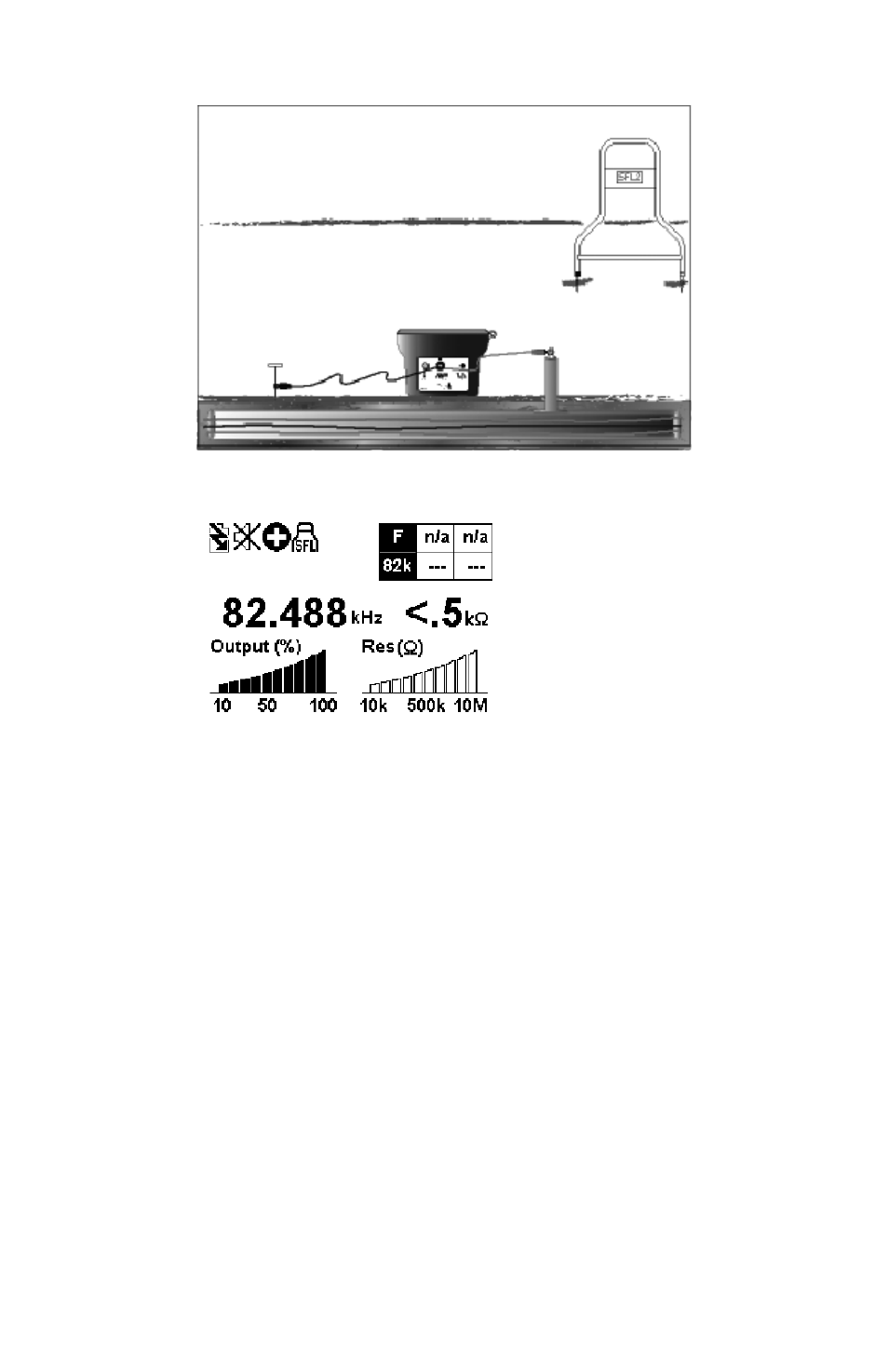
Push T-5000 transmitter SFL key. Check measured fault resistance on transmitter display. See Figure 3-2
6.
Fault Severity Guide:
0-100 KΩ – Severe Fault
100 – 500 KΩ – Medium Fault
1 MΩ and above – Light Faults
Figure 3-2: Transmitter display in SFL mode
Select frequency - 9.8 KHz or 82 KHz, pressing the f button on the Transmitter keypad.
7.
Use the R-5000 Utility Line Locator Receiver to Trace the Cable
5.
Press the frequency softkey (Freq) on the receiver until the frequency selected on the transmitter is displayed. Trace and mark
the cable as you proceed towards the fault.
Synchronize the A-5000 A-Frame Receiver and Establish Reference Value of Fault
6.
(A-Frame receiver has a one-color band above each spike (Black or White)
Hold the A-5000 Receiver so the spike with the Black band is about two (2) steps away from the ground rod and the spike
1.
with the white band is in-line with the targeted cable. The A-5000 receiver must be placed as shown in Figure 3-3 for
synchronization and for unit to operate correctly. Push the A-5000 spikes firmly into the ground. Turn the A-5000 ON.
Wait until the arrow flashes.