Amprobe A-5000 Sheath Fault Locator User Manual
Page 12
Advertising
10
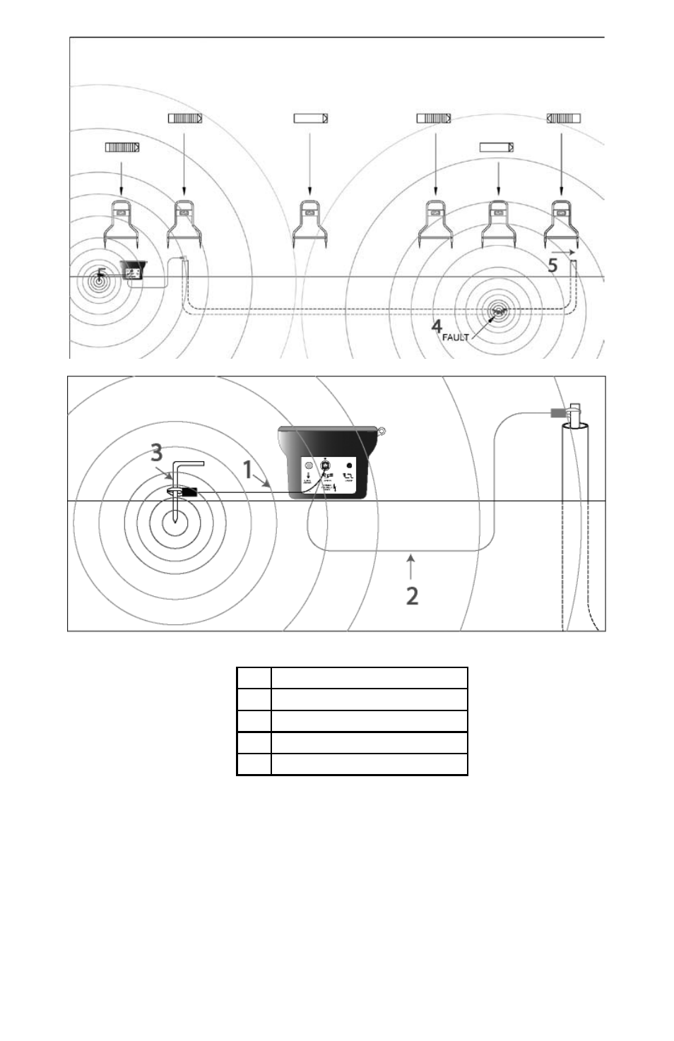
Figure 5-1: Typical T-5000 Transmitter Connection
1
Black Lead
2
Red Lead
3
Ground Rod
4
Fault
5
Faulty conductor open on both ends
As current flows from the transmitter and through the fault, an earth voltage gradient field is created. Its center is at the
fault. This gradient field has a pattern as depicted in Figure 5-2, like pond water ripples when you throw a rock in it or
the rings of a tree stump.)
Advertising
See also other documents in the category Amprobe Measuring instruments:
- AC71B Clamp-On-Multimeter (96 pages)
- AC50A (78 pages)
- ACD-10-TRMS-Pro (16 pages)
- AC68C Clamp-Multimeter (52 pages)
- ACD-14-TRMS-FX Clamp-On-Multimeter (19 pages)
- ACD-10-TRMS-PLUS ACD-10-PLUS Clamp-Multimeters (116 pages)
- ACD-40PQ Clamp-Meters (16 pages)
- ACD-23SW Digital-Clamp-Meters (20 pages)
- ACD-41PQ Clamp-On-Power-Meters (20 pages)
- ACD-41PQ Clamp-On-Power-Meters (121 pages)
- ACD-14-TRMS-PLUS Clamp-On-Multimeters (148 pages)
- ACD-330T Clamp-On-Multimeter (42 pages)
- ACD-21SWC Digital-Clamp-Meters (84 pages)
- ACD-4 Mini-Clamp-DMM (16 pages)
- ACD-6-TRMS-PRO Clamp-On-Multimeters (15 pages)
- FLASH-80 Industrial-Mini-Flashlight (44 pages)
- FLASH-80 Industrial-Mini-Flashlight (98 pages)
- FLASH-80 Industrial-Mini-Flashlight (64 pages)
- FLASH-80 Industrial-Mini-Flashlight (46 pages)
- ACD-50NAV ACD-51NAV ACDC-52NAV ACD-53NAV ACD-54NAV Navigator-Clamps (36 pages)
- ACD-55HPQ Clamp-Meter (62 pages)
- ACDC-620T Clamp-On-Multimeter (65 pages)
- ACDC-400 Digital-Clamp-On-Multimeter (98 pages)
- ACDC-100-TRMS Clamp-On-Multimeters (97 pages)
- RS-3 Rotary-Scale-Clamp-On (4 pages)
- AD105A Clamp-Meter (34 pages)
- LH41A Clamp-On-Ammeter (53 pages)
- 30XR-A Professional-Digital-Multimeter (53 pages)
- 33XR-A Professional-Digital-Multimeter (73 pages)
- 34XR-A Professional-Digital-Multimeter (73 pages)
- 37XR-A Professional-Digital-Multimeter (86 pages)
- 5XP-A 15XP-A 35XP-A Compact-Digital-Multimeters (126 pages)
- AM-110-TRMS Digital-Multimeters (15 pages)
- AM-160-A DMM (30 pages)
- 38XR-A Professional-Digital-Multimeter (92 pages)
- AM-33 Digital-Multimeter (1 page)
- AM-34 Auto-Digital-Multimeter (1 page)
- AM-47 Multimeters (8 pages)
- AM-240 Digital-Multimeters (75 pages)
- AM-250 Digital-Multimeter (22 pages)
- AM-270 Industrial-Multimeter (28 pages)
- AM-60 Compact-Digital-Multimeter (20 pages)
- AM8C Analog-Multimeter (66 pages)
- CR50A Capacitance-Resistance-Meter (46 pages)
- AM91RS Digital-Multimeter (30 pages)