Amprobe A-5000 Sheath Fault Locator User Manual
Page 14
12
F1
F2
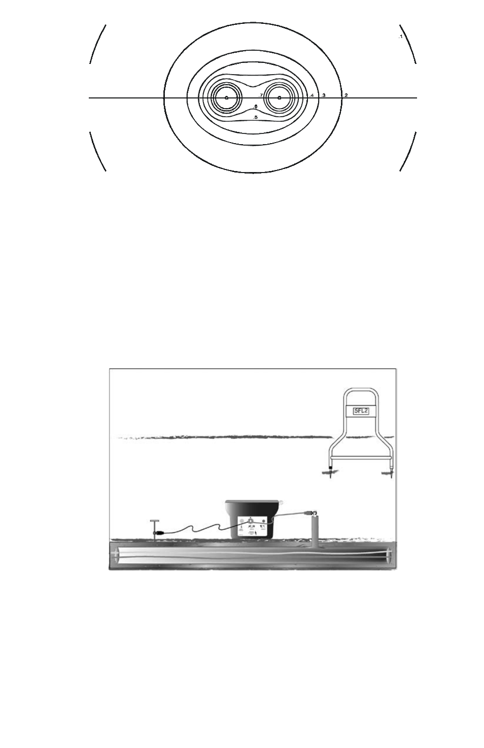
Figure 5-3: Multiple Fault Signal Patterns
Distortion Due to Adjacent Conductors
Whenever a non-insulated adjacent conductor lies between a fault and the ground return point, the return current tends to
concentrate on the conductor instead of flowing through the earth. This situation can shrink the signal pattern near the fault,
which would tend to reduce the detectable signal away from the fault. Possible distortion problems such as the described
situation can be avoided by first tracing the faulty conductor and looking for adjacent conductors prior to fault locating.
CALIBRAtIoN tESt PRoCEdURE
Perform this instrument test procedure on a lawn prior to field site use. If grass or dirt is not available, indoor carpeting may be
used.
Check the Batteries
1.
Turn the T-5000 transmitter ON. The transmitter LCD will display the battery capacity level. Ensure the transmitter battery is
fully charged for optimal operation. Turn the transmitter OFF.
Turn the A-5000 Receiver ON. The solid bars indicate the battery level. If only one bar appears, replace the battery (1 each,
9V). The battery status is ON for 3 seconds at turn on.
Connect the Test Cables
2.
Connect the Black and red connection leads to the transmitter OUTPUT JACK. See Figure 6-1.
Figure 6-1: Checkout Test Set-Up
Spread the Test Leads as Far Apart as Possible
3.
Insert the ground spike and attach the Black cable. Insert a screwdriver into the ground and connect the Red cable to it,
creating a simulated fault.
This test can also be done by pushing the metal end of the clamps directly into the ground so that they make electrical
contact. When using a carpet in this checkout procedure connect test cable clamps directly to the carpet.
Push the SFL T-5000 transmitter button on the keypad
4.
Wait for the SFL high-voltage output to be generated and observe the fault resistance transmitter display.
Synchronize the Receiver
5.
Hold the A-5000 so that the black spike is closer to the ground connection. Push the A-Frame firmly into the ground.
Push the A-5000 Receiver On/Off Switch to ON
6.