5 connecting ipoe-e174 to powered device (pd) – PLANET IPOE-E174 User Manual
Page 17
17
Step 2: The PSE delivers both Ethernet Data and PoE power over
UTP cable to the IPOE-E174 and the “PoE IN” LED will be lit
steadily.
Note
1. When the LED turns steady green, it means the
IPOE-E174 is being powered successfully with PoE.
2. If the LED is not lit, please check the remote PSE or
the cable connecting to a PC or a network device to
see if the cable is correct. Or with an 802.3at device
such as the target PD, check whether the power
injection is correct.
3. Never connect any non-standard POE PSE to the
IPOE-E174, it will damage the device permanently.
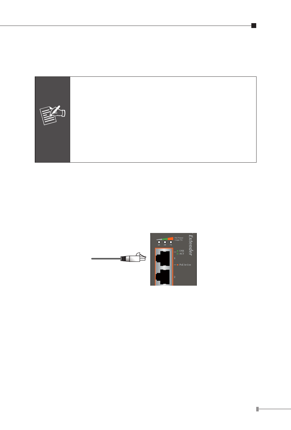
2.5 Connecting IPOE-E174 to Powered Device (PD)
Step 1: Connect the additional CAT-5e/6 cable that will be used to
connect to the remote Powered Device (PD) to the “PoE
In-Use” port of the IPOE-E174.
Step 2: The “PoE In-Use” port is also the power injector which
transmits DC voltage to the CAT-5e/6 cable and transfer data
and power simultaneously between the PSE and PD.