ProSoft Technology MVI69-DNPSNET User Manual
Page 69
Reference MVI69-DNPSNET
♦ CompactLogix or MicroLogix Platform
Distributed Network Protocol Interface Module
ProSoft Technology, Inc.
Page 69 of 119
November 3, 2008
Read Block
These blocks of data transfer information from the module to the CompactLogix
processor. The structure of the input image used to transfer this data is shown
below:
Offset Description
0
Read Block ID
1
Write Block ID
2 to n Read
Data
where
n = 60, 120, or 240 depending on the Block Transfer Size parameter (refer to the configuration file).
The Read Block ID is an index value used to determine the location of where the
data will be placed in the CompactLogix or MicroLogix processor controller tag
array of module read data. The number of data words per transfer depends on
the configured Block Transfer Size parameter in the configuration file (possible
values are 60, 120, or 240).
The Write Block ID associated with the block requests data from the
CompactLogix or MicroLogix processor. Under normal, program operation, the
module sequentially sends read blocks and requests write blocks. For example, if
three read and two write blocks are used with the application, the sequence will
be as follows:
R1W1
R2W2
R3W1
R1W2
R2W1
R3W2
R1W1
This sequence will continue until interrupted by other write block numbers sent by
the controller or by a command request from a node on the DNP network or
operator control through the module's Configuration/Debug port.
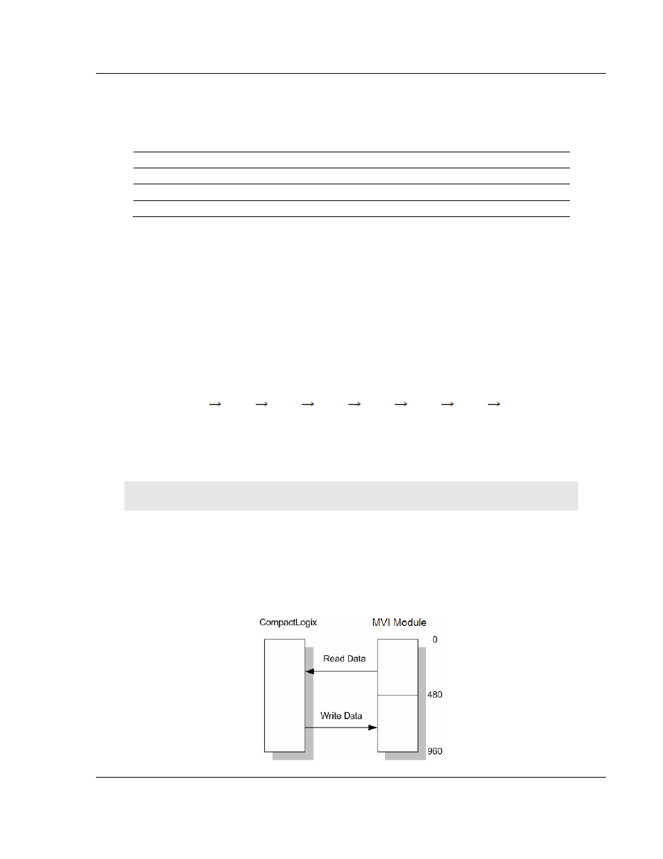
The following example shows a typical backplane communication application.
Note: This example for reference only
Assume that the backplane parameters are configured as follows:
Read Register Start: 0
Read Register Count: 480
Write Register Start: 480
Write Register Count: 480
The backplane communication would be configured as follows: