1 dc power input sigma-v series servopacks, 2 part names, 1 dc power input σ -v series servopacks – Yaskawa Σ-V Series AC Servo Drives Rotational Motor MECHATROLINK-III User Manual
Page 20: M-iii
1 Outline
1-2
1.1
DC Power Input
Σ
-V Series SERVOPACKs
The DC Power Input
Σ
-V Series SERVOPACKs are designed for applications that require frequent high-
speed, high-precision positioning. The SERVOPACK makes the most of machine performance in the
shortest time possible, thus contributing to improving productivity.
1.2
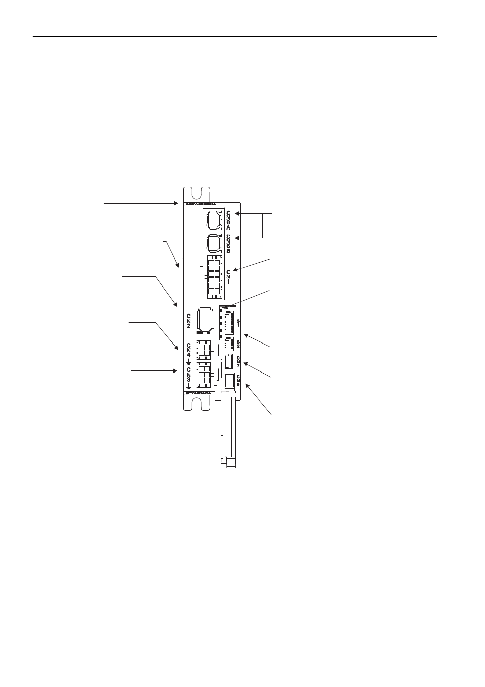
Part Names
This section describes the part names of SGDV SERVOPACK for MECHATROLINK-III communications
reference.
DIP Switches (S1 and S2)
Used to set MECHATROLINK-
III
communications.
LED indicator (LK1, LK2, CON, RDY, ALM)
LK1, LK2 (green): Lights during MECHATROLINK communications.
CON (green): Lights when the SERVOPACK correctly receives the
CONNECT command.
SERVOPACK model
Nameplate (Found on side of SERVOPACK.)
Indicates the SERVOPACK model and ratings.
CN2 Connector for encoder
Connects the encoder in the servomotor.
CN4 Connector for servomotor
Connects the main circuit cable for servomotor.
CN3 Connector for power supply
Used for main circuit or control power supply input.
CN1 Connector for I/O signal
Used for reference input signals and sequence I/O signals.
CN6A/CN6B Connectors for MECHATROLINK-
III
communications
Connects MECHATROLINK-
III
-supported devices.
RDY (green): Lights when the SERVOPACK is
in Servo Ready status without alarm.
ALM (red): Lights when an alarm occurs.
CN5 Connector for external monitor
Used for Connection cable (model: JZSP-CF1S06-A3-E) connected to
the analog monitor unit serving as a hub (model:
JUSP-PC001-E) to which a cable specially for the actual
analog monitor is connected.
When not in use, cover this connector.
CN7 Connector for personal computer (USB connector)
Communicates with a personal computer.
Use the connection cable (model: JZSP-CVS06-02-E).
When not in use, cover this connector.
M-III
Refer to
1.6 SERVOPACK Model Designation
.
Refer to
3.6 Encoder Connection
.
Refer to
3.1 Main Circuit Wiring
.
Refer to
3.1 Main Circuit Wiring
.
Refer to
3.5 Wiring MECHATROLINK-
III
Communi-
cations
.
Refer to
3.2 I/O Signal Connections
.
Refer to
4.1.1 Setting Switches S1 and S2
.
Refer to
1.5 Examples of Servo System Configurations
.