Circuit board header connection, Circuit board header connection –3 – Altera EthernetBlaster II User Manual
Page 27
Chapter 3: EthernetBlaster II Communications Cable Specifications
3–3
EthernetBlaster II Hardware Connections
January 2014
Altera Corporation
EthernetBlaster II Communications Cable User Guide
1
The circuit board must supply V
CC(TARGET)
and ground to the EthernetBlaster II cable
for the I/O drivers.
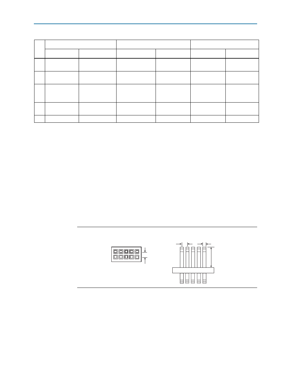
Circuit Board Header Connection
The circuit board’s 10-pin male header, which connects to the EthernetBlaster II
cable’s 10-pin female plug, has two rows of five pins. These pins are connected to the
device’s programming or configuration pins.
shows the dimensions of a
typical 10-pin male header.
1
Although you can use a 10-pin surface mount header for the Joint Test Action Group
(JTAG), active serial (AS), or passive serial (PS) download cable, Altera recommends
using a through-hole connector because of the repeated insertion and removal force
needed.
6
nCE
Cyclone chip
enable
—
No connect
—
No connect
7
DATAOUT
Active serial data
out
nSTATUS
Configuration
status
—
No connect
8
nCS
Serial
configuration
device chip select
—
No connect
—
No connect
9
ASDI
Active serial data
in
DATA0
Data to device
TDI
Data to device
10
GND
Signal ground
GND
Signal ground
GND
Signal ground
Table 3–2. EthernetBlaster Female Plug Signal Names and Programming Modes (Part 2 of 2)
Pin
AS Mode
PS Mode
JTAG Mode
Signal Name
Description
Signal Name
Description
Signal Name
Description
Figure 3–3. 10-Pin Male Header Dimensions
o
0.025 Sq.
0.235
0.100
0.100
Dimensions are shown in inches.
Top View
Side View