Altera EthernetBlaster II User Manual
Page 8
1–4
Chapter 1: Installing the EthernetBlaster II Communications Cable
Cable Setup
EthernetBlaster II Communications Cable User Guide
January 2014
Altera Corporation
■
“Configuring the EthernetBlaster II Hardware to Use Static IP Addressing” on
page 1–9
■
“Configuring the EthernetBlaster II Hardware to Use Dynamic IP Addressing” on
page 1–10
■
“Setting Up the EthernetBlaster II Hardware in the Quartus II Software” on
page 1–11
■
“Removing the EthernetBlaster II Hardware from the Quartus II Software” on
page 1–12
1
For plug and header dimensions, pin names, and operating conditions, refer to
“EthernetBlaster II Communications Cable Specifications” on page 3–1
Using the Network with Default Factory Settings for Remote Connections
Use the following steps to connect remotely to the EthernetBlaster II communications
cable:
1
These steps assume no changes have been made to the default factory settings.
1. Power off the target circuit board.
2. Plug one end of a standard CAT 5 UTP 4-pair patch cable into the Ethernet jack on
the EthernetBlaster II communications cable and the other end into a network port
of a switch, router, or hub (
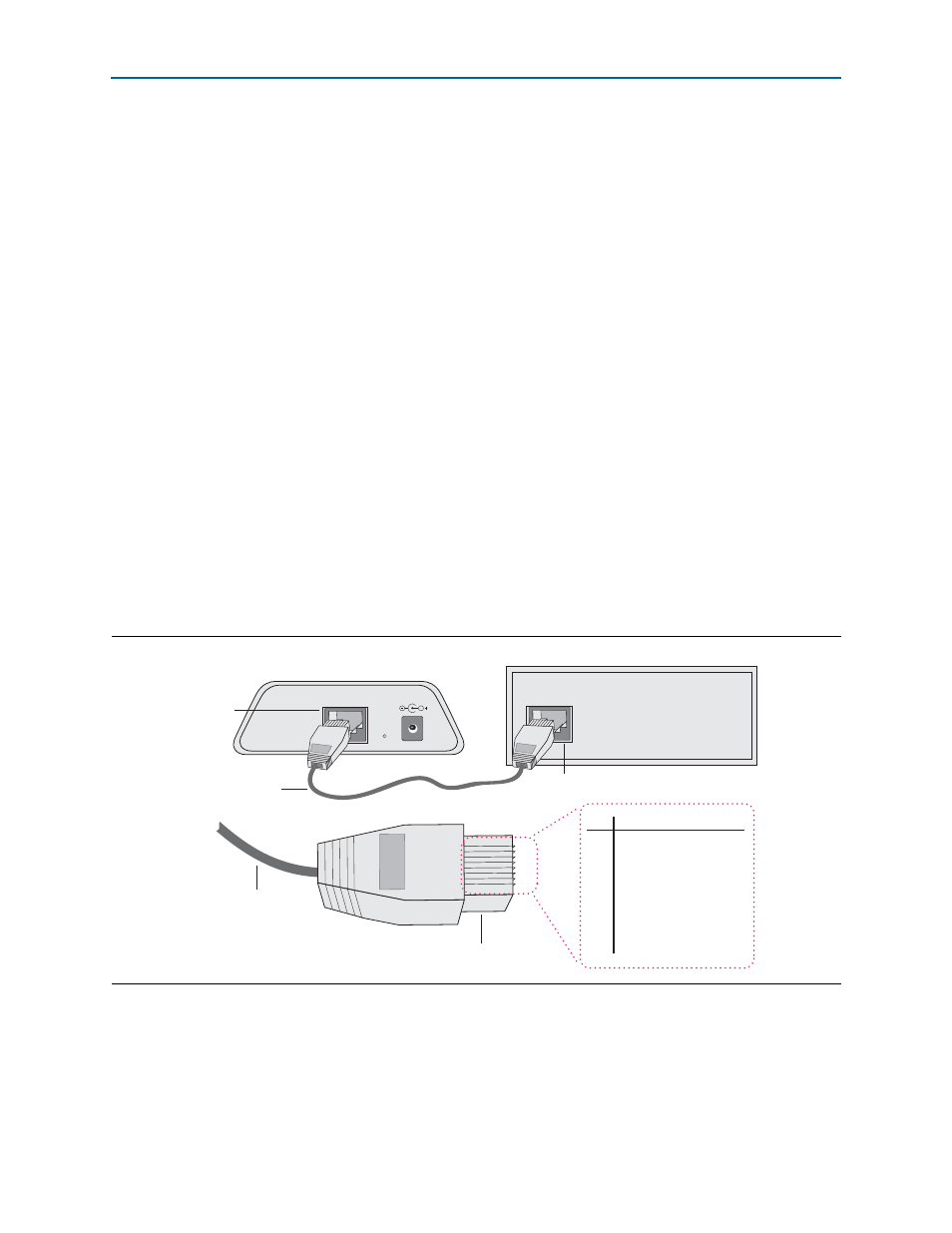
Figure 1–2. Remote Connection Using the Network
Switch, Router, or Hub
ETHERNET
ETHERNET
DC12V
EthernetBlaster Communications Cable,
Ethernet Port Side View
CAT 5 UTP
Standard Cable
Ethernet Jack
CAT 5 UTP
Standard Cable
Ethernet Connector
EIA/TIA 568B
1
.
.
.
8
Pin
EIA/TIA 568B Wire Color
1
2
3
4
5
6
7
8
White with
Orange
Stripe
Orange
with White Stripe
White with
Green
Stripe
Blue
with White Stripe
White with
Blue
Stripe
Green
with White Stripe
White with
Brown
Stripe
Brown
with White Stripe
Ethernet
Jack