Static and dynamic ip addressing, Cable setup, Static and dynamic ip addressing –3 – Altera EthernetBlaster II User Manual
Page 7: Cable setup –3
Chapter 1: Installing the EthernetBlaster II Communications Cable
1–3
Cable Setup
January 2014
Altera Corporation
EthernetBlaster II Communications Cable User Guide
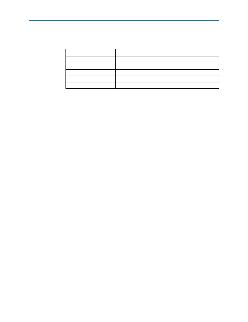
The status LED on the target port side of the cable displays the operating status of the
EthernetBlaster II communications cable.
lists each LED status mode.
Static and Dynamic IP Addressing
The EthernetBlaster II communications cable supports both static IP and dynamic IP
addressing, the latter by means of the dynamic host configuration protocol (DHCP).
By default, the EthernetBlaster II cable is configured at the factory to use dynamic IP
addressing. After power up, the cable attempts to obtain an IP address from your
network DHCP server. The status LED is green and blinking while the network
address is being obtained and the cable is initializing. This process may take up to two
minutes.
After an IP address is obtained and the cable is ready to use, the status LED emits a
steady green light. If the attempt to obtain an IP address is unsuccessful (the DHCP
server may be down or absent), the cable switches to static IP addressing. The default
IP address is configured to 192.168.0.50. If you use static IP addressing, you must
configure your computer to an IP address in the same subnet as the cable to
communicate with it. The default setting requires your address to be in the 192.168.0.X
network domain.
1
Refer to your operating system manual or contact your network administrator to
verify that your network supports DHCP services and for instruction on how to
change your IP address.
To maintain your computer’s IP address and change the EthernetBlaster II
communications cable’s default IP address, refer to
EthernetBlaster II Hardware to Use Static IP Addressing” on page 1–9
.
The EthernetBlaster II communications cable includes a self-hosted administrative
web page, allowing you to configure various aspects of cable operation. The following
section describes how to access this web page based on your mode of connection.
Cable Setup
This section describes how to install and set up the EthernetBlaster II communications
cable for device configuration or programming using the following setups:
■
“Using the Network with Default Factory Settings for Remote Connections” on
page 1–4
■
“Using the Default Factory Settings for a Direct Connection to a Computer” on
page 1–7
Table 1–1. Status LED Modes
Status LED
Status Description
Yellow, blinking
Power on, reset
Green, blinking
Cable initialization
Green, steady
Cable ready, DHCP
Blue, blinking
Downloading data to the target PCB
Purple, blinking
Updating EthernetBlaster II firmware